Lexus ES: Inspection
INSPECTION
PROCEDURE
1. INSPECT PORT FUEL INJECTOR ASSEMBLY
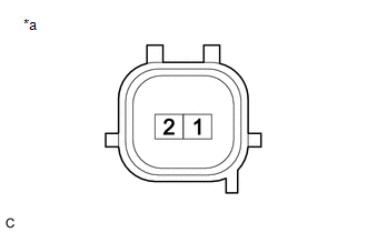
(a) Check the resistance.
| (1) Measure the resistance according to the value(s) in the table below. Standard Resistance:
If the result is not as specified, replace the port fuel injector assembly. |
|
(b) Check the operation.
CAUTION:
Perform the inspection in a well-ventilated area.
Do not perform the inspection near an open flame.
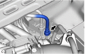
| (1) Disengage the 2 claws to remove the No. 2 fuel pipe clamp. |
|
.png)
| (2) Remove the fuel pipe clamp from the fuel tube connector. |
|
.png)
| (3) Disconnect the fuel tube sub-assembly. Click here |
|
| (4) Connect SST (fuel tube connector) to SST (hose) with SST (hose band), and then connect them to the fuel pipe (vehicle side). SST: 09268-31015 09268-41500 09268-41700 95336-08070 NOTICE: Make sure the SST (fuel tube connector) O-rings are not damaged and are free of foreign matter as they are used to seal the connections between the fuel tube connector and fuel pipe. |
|
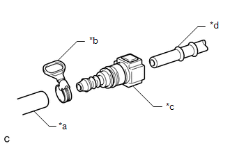
(5) Apply a light coat of gasoline to a new O-ring, and then install the O-ring to the port fuel injector assembly.
| (6) Connect SST (adapter) and SST (hose) to the port fuel injector assembly, and hold the port fuel injector assembly and union with SST (clamp). SST: 09268-31015 09268-41600 09268-41300 09268-41700 95336-08070 |
|
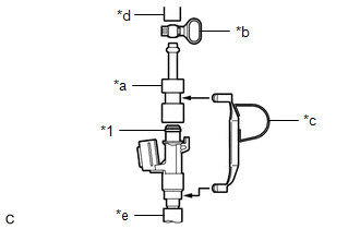
| (7) Tie SST (clamp) and SST (adapter) together with SST (tie band) as shown in the illustration. SST: 09268-31015 09268-41800 NOTICE:
HINT: When removing SST (tie band), disengage the lock. |
|
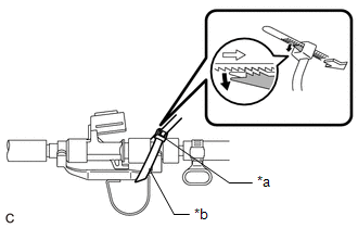
(8) Check that SST (clamp) and SST (adapter) cannot be easily separated.
(9) Install a vinyl tube to the port fuel injector assembly.
CAUTION:
Install a suitable vinyl tube to the port fuel injector assembly to prevent fuel from spraying.
(10) Set the port fuel injector assembly into a graduated cylinder.
(11) Connect the Techstream to the DLC3.
(12) Turn the engine switch on (IG).
NOTICE:
Do not start the engine.
(13) Turn the Techstream on.
(14) Enter the following menus: Powertrain / Engine / Active Test / Activate the Circuit Relay.
Powertrain > Engine > Active Test| Tester Display |
|---|
| Activate the Circuit Relay |
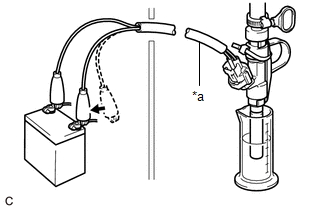
| (15) Connect SST (EFI inspection wire I) to the port fuel injector assembly and battery for 15 seconds, and measure the injection volume with the graduated cylinder. Test each port fuel injector assembly 2 or 3 times. SST: 09842-30090 Standard Injection Volume:
Difference between Each Port Fuel Injector Assembly: 14 cc (0.9 cu. in.) or less NOTICE:
If the injection volume is not as specified, replace the port fuel injector assembly. |
|
(c) Check for leaks.
(1) Disconnect SST (EFI inspection wire I) from the battery and check for fuel leaks from the port fuel injector assembly.
Standard Fuel Drop:
1 drop or less per 20 minutes
If the result is not as specified, replace the port fuel injector assembly.
(2) Connect the fuel tube sub-assembly.
Click here .gif)
(3) Install the fuel pipe clamp to the fuel tube connector.
(4) Engage the 2 claws to install the No. 2 fuel pipe clamp.
(5) Check for fuel leaks.
Click here
READ NEXT:
 Installation
INSTALLATION PROCEDURE 1. INSTALL PORT FUEL INJECTOR ASSEMBLY HINT: Perform "Inspection After Repair" after replacing a port fuel injector assembly. Click here (a) Apply a light coat of spindle oil
Components
COMPONENTS ILLUSTRATION *1 FUEL SUCTION PLATE SUB-ASSEMBLY *2 FUEL FILTER *3 O-RING *4 FUEL MAIN VALVE ASSEMBLY (for Low Pressure) *5 FUEL MAIN VALVE ASSEMBLY (for High Press
SEE MORE:
Installation
INSTALLATION PROCEDURE 1. INSTALL NO. 1 BACK WINDOW GLASS STOPPER (for 2-piece Type) (a) Install 2 new No. 1 back window glass stoppers to the vehicle body as shown in the illustration. HINT: Only 2-piece type back window glass stoppers are provided as supply parts. Use 2-piece type stoppers as r
Torque Converter Clutch Actuator Stuck On (P07407E)
DESCRIPTION The ECM uses signals from the throttle position sensor, mass air flow meter, transmission revolution sensor (NT), transmission revolution sensor (NC) and crankshaft position sensor to help determine the engagement timing of the lock-up clutch. The ECM monitors the engagement of the clutc
