Lexus ES: Removal
REMOVAL
CAUTION / NOTICE / HINT
The necessary procedures (adjustment, calibration, initialization or registration) that must be performed after parts are removed and installed, or replaced during VVT sensor removal/installation are shown below.
Necessary Procedures After Parts Removed/Installed/Replaced| Replaced Part or Performed Procedure | Necessary Procedure | Effect/Inoperative Function when Necessary Procedure not Performed | Link |
|---|---|---|---|
| Inspection after repair |
| |
PROCEDURE
1. REMOVE INTAKE AIR SURGE TANK ASSEMBLY
Click here .gif)
2. REMOVE VVT SENSOR (for Intake Side of Bank 1)
| (a) Disconnect the VVT sensor connector. |
|
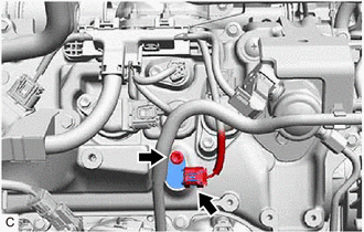
(b) Remove the bolt and VVT sensor from the cylinder head cover sub-assembly.
NOTICE:
If the VVT sensor has been struck or dropped, replace it.
3. REMOVE VVT SENSOR (for Exhaust Side of Bank 1)
| (a) Disconnect the VVT sensor connector. |
|
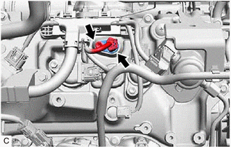
(b) Remove the bolt and VVT sensor from the cylinder head cover sub-assembly.
NOTICE:
If the VVT sensor has been struck or dropped, replace it.
4. REMOVE VVT SENSOR (for Intake Side of Bank 2)
| (a) Disconnect the VVT sensor connector. |
|
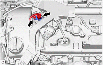
(b) Remove the bolt and VVT sensor from the cylinder head cover sub-assembly LH.
NOTICE:
If the VVT sensor has been struck or dropped, replace it.
5. REMOVE VVT SENSOR (for Exhaust Side of Bank 2)
| (a) Disconnect the VVT sensor connector. |
|
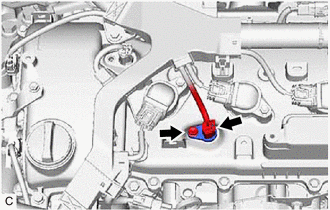
(b) Remove the bolt and VVT sensor from the cylinder head cover sub-assembly LH.
NOTICE:
If the VVT sensor has been struck or dropped, replace it.
READ NEXT:
 Installation
INSTALLATION PROCEDURE 1. INSTALL VVT SENSOR (for Exhaust Side of Bank 2) (a) Apply a light coat of engine oil to the O-ring of the VVT sensor. NOTICE: If reusing the VVT sensor, be sure to inspect th
Crankshaft Position Sensor
ComponentsCOMPONENTS ILLUSTRATION *1 CRANKSHAFT POSITION SENSOR *2 CRANKSHAFT POSITION SENSOR PROTECTOR N*m (kgf*cm, ft.*lbf): Specified torque - - RemovalREMOVAL CAUTION / N
SEE MORE:
Front Camera Internal Circuit (C2A60)
DESCRIPTION This DTC is stored when the parking assist ECU detects a signal indicating a malfunction in the front television camera assembly via CAN communication. DTC No. Detection Item DTC Detection Condition Trouble Area C2A60 Front Camera Internal Circuit A signal indicating a m
Open in Bus 3 Main Bus Line
DESCRIPTION There may be an open circuit in one of the CAN main bus lines when the resistance between terminals 6 (CA3H) and 21 (CA3L) of the central gateway ECU (network gateway ECU) is 70 Ω or higher. Symptom Trouble Area Resistance between terminals 6 (CA3H) and 21 (CA3L) of the central
