Lexus ES: Crankshaft Position Sensor
Components
COMPONENTS
ILLUSTRATION
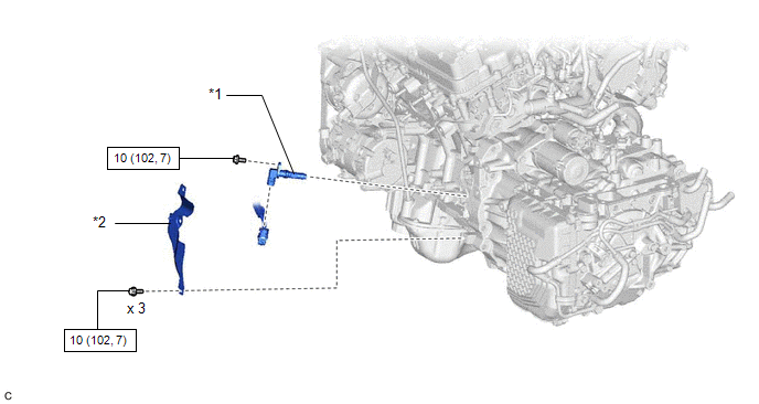
| *1 | CRANKSHAFT POSITION SENSOR | *2 | CRANKSHAFT POSITION SENSOR PROTECTOR |
.png) | N*m (kgf*cm, ft.*lbf): Specified torque | - | - |
Removal
REMOVAL
CAUTION / NOTICE / HINT
The necessary procedures (adjustment, calibration, initialization or registration) that must be performed after parts are removed and installed, or replaced during crankshaft position sensor removal/installation are shown below.
Necessary Procedures After Parts Removed/Installed/Replaced| Replaced Part or Performed Procedure | Necessary Procedure | Effect/Inoperative Function when Necessary Procedure not Performed | Link |
|---|---|---|---|
| Gas leak from exhaust system is repaired | Inspection after repair |
| |
PROCEDURE
1. REMOVE EXHAUST MANIFOLD SUB-ASSEMBLY LH (TWC: Front Catalyst)
Click here .gif)
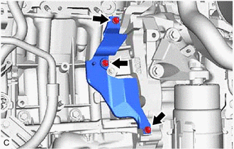
2. REMOVE CRANKSHAFT POSITION SENSOR PROTECTOR
| (a) Remove the 3 bolts and crankshaft position sensor protector from the cylinder block sub-assembly and oil pan sub-assembly. |
|
3. REMOVE CRANKSHAFT POSITION SENSOR
| (a) Disconnect the crankshaft position sensor connector. |
|
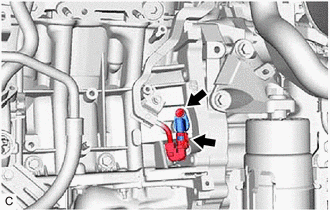
(b) Remove the bolt and crankshaft position sensor from the cylinder block sub-assembly.
NOTICE:
If the crankshaft position sensor has been struck or dropped, replace it.
Installation
INSTALLATION
PROCEDURE
1. INSTALL CRANKSHAFT POSITION SENSOR
(a) Apply a light coat of engine oil to the O-ring of the crankshaft position sensor.
NOTICE:
If reusing the crankshaft position sensor, be sure to inspect the O-ring.
(b) Install the crankshaft position sensor to the cylinder block sub-assembly with the bolt.
Torque:
10 N·m {102 kgf·cm, 7 ft·lbf}
NOTICE:
- If the crankshaft position sensor has been struck or dropped, replace it.
- Make sure that the O-ring is not cracked or moved out of place when installing the crankshaft position sensor.
(c) Connect the crankshaft position sensor connector.
2. INSTALL CRANKSHAFT POSITION SENSOR PROTECTOR
(a) Install the crankshaft position sensor protector to the cylinder block sub-assembly and oil pan sub-assembly with the 3 bolts.
Torque:
10 N·m {102 kgf·cm, 7 ft·lbf}
3. INSTALL EXHAUST MANIFOLD SUB-ASSEMBLY LH (TWC: Front Catalyst)
Click here .gif)
READ NEXT:
 Components
COMPONENTS ILLUSTRATION *1 AIR CLEANER ASSEMBLY WITH AIR CLEANER HOSE *2 COOL AIR INTAKE DUCT SEAL *3 ECM *4 INLET AIR CLEANER ASSEMBLY *5 NO. 1 ECM BRACKET *6 NO. 2 ECM
Removal
REMOVAL CAUTION / NOTICE / HINT The necessary procedures (adjustment, calibration, initialization or registration) that must be performed after parts are removed and installed, or replaced during ECM
SEE MORE:
Generator Position Sensor Circuit "A" Circuit Open (P0C6413,P0C641F,P0C6913,P0C691F)
DTC SUMMARY MALFUNCTION DESCRIPTION These DTCs indicate that the resolver output signal is abnormal. The cause of this malfunction may be one of the following: Area Main Malfunction Description Inverter low-voltage circuit The connectors are not connected properly Hybrid Vehicle Trans
G Sensor Failure (C1647)
DESCRIPTION The clearance warning sonar ECU assembly communicates with the airbag sensor assembly (yaw rate and acceleration sensor) via CAN communication, and if it is determined that the airbag sensor assembly (yaw rate and acceleration sensor) is malfunctioning, DTC C1647 is stored. DTC No.
