Lexus ES: Installation
INSTALLATION
PROCEDURE
1. INSTALL VVT SENSOR (for Exhaust Side of Bank 2)
(a) Apply a light coat of engine oil to the O-ring of the VVT sensor.
NOTICE:
If reusing the VVT sensor, be sure to inspect the O-ring.
(b) Clean the bolt and bolt hole.
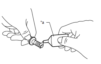
| (c) Apply adhesive to 2 or 3 threads at the end of the bolt. Adhesive: Toyota Genuine Adhesive 1324, Three Bond 1324 or equivalent |
|
(d) Install the VVT sensor to the cylinder head cover sub-assembly LH with the bolt.
Torque:
10 N·m {102 kgf·cm, 7 ft·lbf}
NOTICE:
- If the VVT sensor has been struck or dropped, replace it.
- Make sure that the O-ring is not cracked or moved out of place when installing the VVT sensor.
(e) Connect the VVT sensor connector.
2. INSTALL VVT SENSOR (for Intake Side of Bank 2)
(a) Apply a light coat of engine oil to the O-ring of the VVT sensor.
NOTICE:
If reusing the VVT sensor, be sure to inspect the O-ring.
(b) Clean the bolt and bolt hole.
| (c) Apply adhesive to 2 or 3 threads at the end of the bolt. Adhesive: Toyota Genuine Adhesive 1324, Three Bond 1324 or equivalent |
|
(d) Install the VVT sensor to the cylinder head cover sub-assembly LH with the bolt.
Torque:
10 N·m {102 kgf·cm, 7 ft·lbf}
NOTICE:
- If the VVT sensor has been struck or dropped, replace it.
- Make sure that the O-ring is not cracked or moved out of place when installing the VVT sensor.
(e) Connect the VVT sensor connector.
3. INSTALL VVT SENSOR (for Exhaust Side of Bank 1)
(a) Apply a light coat of engine oil to the O-ring of the VVT sensor.
NOTICE:
If reusing the VVT sensor, be sure to inspect the O-ring.
(b) Clean the bolt and bolt hole.
| (c) Apply adhesive to 2 or 3 threads at the end of the bolt. Adhesive: Toyota Genuine Adhesive 1324, Three Bond 1324 or equivalent |
|
(d) Install the VVT sensor to the cylinder head cover sub-assembly with the bolt.
Torque:
10 N·m {102 kgf·cm, 7 ft·lbf}
NOTICE:
- If the VVT sensor has been struck or dropped, replace it.
- Make sure that the O-ring is not cracked or moved out of place when installing the VVT sensor.
(e) Connect the VVT sensor connector.
4. INSTALL VVT SENSOR (for Intake Side of Bank 1)
(a) Apply a light coat of engine oil to the O-ring of the VVT sensor.
NOTICE:
If reusing the VVT sensor, be sure to inspect the O-ring.
(b) Clean the bolt and bolt hole.
| (c) Apply adhesive to 2 or 3 threads at the end of the bolt. Adhesive: Toyota Genuine Adhesive 1324, Three Bond 1324 or equivalent |
|
(d) Install the VVT sensor to the cylinder head cover sub-assembly with the bolt.
Torque:
10 N·m {102 kgf·cm, 7 ft·lbf}
NOTICE:
- If the VVT sensor has been struck or dropped, replace it.
- Make sure that the O-ring is not cracked or moved out of place when installing the VVT sensor.
(e) Connect the VVT sensor connector.
5. INSTALL INTAKE AIR SURGE TANK ASSEMBLY
Click here .gif)
6. INSPECT FOR ENGINE OIL LEAK
Click here
READ NEXT:
 Crankshaft Position Sensor
ComponentsCOMPONENTS ILLUSTRATION *1 CRANKSHAFT POSITION SENSOR *2 CRANKSHAFT POSITION SENSOR PROTECTOR N*m (kgf*cm, ft.*lbf): Specified torque - - RemovalREMOVAL CAUTION / N
Components
COMPONENTS ILLUSTRATION *1 AIR CLEANER ASSEMBLY WITH AIR CLEANER HOSE *2 COOL AIR INTAKE DUCT SEAL *3 ECM *4 INLET AIR CLEANER ASSEMBLY *5 NO. 1 ECM BRACKET *6 NO. 2 ECM
SEE MORE:
Sensor (Motor) Failure (B2341,B2344)
DESCRIPTION When the sliding roof ECU (sliding roof drive gear sub-assembly) detects a motor malfunction and the sliding roof operation is stopped, DTC B2341 is stored. When the sliding roof ECU (sliding roof drive gear sub-assembly) detects a gear position malfunction and the sliding roof operation
Driving the vehicle
The following procedures should be
observed to ensure safe driving:
Driving procedure
■ Driving
1. With the brake pedal depressed,
shift the shift lever to D.
2. If the parking brake is in manual
mode, release the parking brake.
3. Gradually release the brake pedal
and gently depress
