Lexus ES: Components
COMPONENTS
ILLUSTRATION
.png)
| *1 | FRONT FENDER APRON SEAL RH | *2 | V-BANK COVER SUB-ASSEMBLY |
.png) | N*m (kgf*cm, ft.*lbf): Specified torque | - | - |
ILLUSTRATION
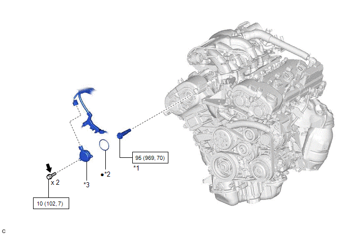
| *1 | CAMSHAFT TIMING GEAR BOLT | *2 | O-RING |
| *3 | CAMSHAFT TIMING OIL CONTROL SOLENOID ASSEMBLY (for Intake Side of Bank 1) | - | - |
| | N*m (kgf*cm, ft.*lbf): Specified torque | ● | Non-reusable part |
.png) | Adhesive 1324 | ★ | Precoated part |
READ NEXT:
 Removal
REMOVAL PROCEDURE 1. REMOVE FRONT WHEEL RH Click here 2. REMOVE FRONT FENDER APRON SEAL RH Click here 3. REMOVE V-BANK COVER SUB-ASSEMBLY Click here 4. REMOVE CAMSHAFT TIMING OIL CONTROL SOL
Inspection
INSPECTION PROCEDURE 1. INSPECT CAMSHAFT TIMING GEAR BOLT (a) Check the stroke of the plunger in the center of the camshaft timing gear bolt. Standard Stroke: 4.5 mm (0.177 in.) or more HINT: When
Installation
INSTALLATION PROCEDURE 1. INSTALL CAMSHAFT TIMING GEAR BOLT (a) Make sure that the No. 1 cylinder is at TDC/compression. HINT: Check that the cutout of the camshaft timing gear assembly is at the top
SEE MORE:
Diagnostic Trouble Code Chart
DIAGNOSTIC TROUBLE CODE CHART Parking Support Brake System DTC No. Detection Item Link C1625 Open or Short in Steering Angle Sensor +B C1626 Steering Angle Sensor Failure C1647 G Sensor Failure C164B Communication Error From Clearance Sonar ECU to VSC
Stop Lamp Relay Actuator Stuck On (C13807E)
DESCRIPTION When any of the following conditions are met, the skid control ECU (brake actuator assembly) sets the drive output (STPO) ON which operates the stop light control relay (stop light switch assembly) and turns on the stop lights. Illumination Conditions:
Pre-collision brake is operating
© 2016-2026 Copyright www.lexguide.net
