Lexus ES: Removal
REMOVAL
PROCEDURE
1. REMOVE FRONT WHEEL RH
Click here .gif)
2. REMOVE FRONT FENDER APRON SEAL RH
Click here
3. REMOVE V-BANK COVER SUB-ASSEMBLY
Click here
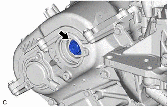
4. REMOVE CAMSHAFT TIMING OIL CONTROL SOLENOID ASSEMBLY (for Intake Side of Bank 1)
Click here
5. SET NO. 1 CYLINDER TO TDC/COMPRESSION
| (a) Turn the crankshaft pulley clockwise until its timing mark (cutout) is aligned with the timing mark on the timing chain cover assembly as shown in the illustration. |
|
.png)
(b) Check that the cutout of the camshaft timing gear assembly is at the top.
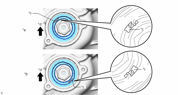
| *a | Correct | *b | Incorrect |
| *c | Cutout | *d | Up |
HINT:
If the cutout of the camshaft timing gear assembly is not at the top, turn the crankshaft 360° clockwise and align the timing mark (cutout) of the crankshaft pulley with the timing mark on the timing chain cover assembly again.
6. REMOVE CAMSHAFT TIMING GEAR BOLT
| (a) While holding the crankshaft pulley, remove the camshaft timing gear bolt. NOTICE:
|
|
READ NEXT:
 Inspection
INSPECTION PROCEDURE 1. INSPECT CAMSHAFT TIMING GEAR BOLT (a) Check the stroke of the plunger in the center of the camshaft timing gear bolt. Standard Stroke: 4.5 mm (0.177 in.) or more HINT: When
Installation
INSTALLATION PROCEDURE 1. INSTALL CAMSHAFT TIMING GEAR BOLT (a) Make sure that the No. 1 cylinder is at TDC/compression. HINT: Check that the cutout of the camshaft timing gear assembly is at the top
SEE MORE:
Components
COMPONENTS ILLUSTRATION *A Type A *B Type B *1 FRONT FENDER APRON SEAL LH *2 FRONT WHEEL OPENING EXTENSION PAD LH *3 FRONT WHEEL OPENING EXTENSION PAD RH *4 NO. 1 ENGINE UNDER COVER *5 NO. 3 ENGINE UNDER COVER - - N*m (kgf*cm, ft.*lbf): Specified torque
Radio Receiver Power Source Circuit
DESCRIPTION This is the power source circuit to operate the radio receiver assembly. WIRING DIAGRAM CAUTION / NOTICE / HINT NOTICE: Inspect the fuses for circuits related to this system before performing the following procedure. PROCEDURE 1. CHECK HARNESS AND CONNECTOR (RADIO RECEIVER ASSEMBL
