Lexus ES: Components
COMPONENTS
ILLUSTRATION
.png)
| *1 | SHIFT LEVER KNOB SUB-ASSEMBLY | *2 | SHIFT LOCK RELEASE BUTTON COVER |
| *3 | TRANSMISSION CONTROL CABLE ASSEMBLY | *4 | TRANSMISSION FLOOR SHIFT ASSEMBLY |
| *5 | REAR UPPER CONSOLE PANEL SUB-ASSEMBLY | *6 | NO. 1 CONSOLE BOX DUCT |
| *7 | UPPER CONSOLE PANEL SUB-ASSEMBLY | - | - |
.png) | N*m (kgf*cm, ft.*lbf): Specified torque | - | - |
ILLUSTRATION
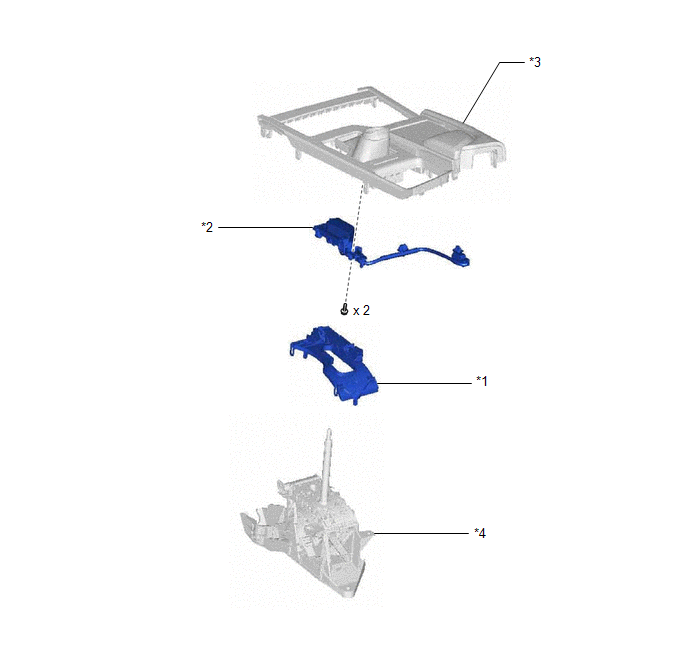
| *1 | LOWER POSITION INDICATOR HOUSING | *2 | SHIFT POSITION INDICATOR |
| *3 | REAR UPPER CONSOLE PANEL SUB-ASSEMBLY | *4 | SHIFT LOCK CONTROL UNIT ASSEMBLY |
READ NEXT:
 Disassembly
DISASSEMBLY PROCEDURE 1. REMOVE SHIFT POSITION INDICATOR (a) Disengage the 2 clamps to disconnect the wire harness. (b) Remove the 2 screws. (c) Disengage the claw and
Inspection
INSPECTION PROCEDURE 1. INSPECT SHIFT LOCK CONTROL ECU HINT: If the results of the following inspections are as specified but a malfunction has occurred, replace the shift lock control unit assembly.
Installation
INSTALLATION PROCEDURE 1. INSTALL TRANSMISSION FLOOR SHIFT ASSEMBLY (a) Engage the clamp to connect the wire harness to the transmission floor shift assembly. (b) Connect the shift lock control ECU co
SEE MORE:
Speaker Output Short (B15C3)
DESCRIPTION This DTC is stored when a malfunction occurs in the speakers. DTC No. Detection Item DTC Detection Condition Trouble Area B15C3 Speaker Output Short A short is detected in the speaker output circuit.
Harness or connector
Speaker
Stereo component amplifier assemb
Indicator (Red) Circuit Short to Ground (B157011,B157013)
DESCRIPTION This DTC is stored when the DCM (telematics transceiver) detects an open or short in the manual (SOS) switch red indicator circuit of the manual (SOS) switch. The manual (SOS) switch red indicator illuminates for 2 seconds and goes off when the engine switch is turned on (IG). If a malfu
© 2016-2026 Copyright www.lexguide.net
