Lexus ES: Speaker Output Short (B15C3)
DESCRIPTION
This DTC is stored when a malfunction occurs in the speakers.
| DTC No. | Detection Item | DTC Detection Condition | Trouble Area |
|---|---|---|---|
| B15C3 | Speaker Output Short | A short is detected in the speaker output circuit. |
|
- *: w/ Manual (SOS) Switch
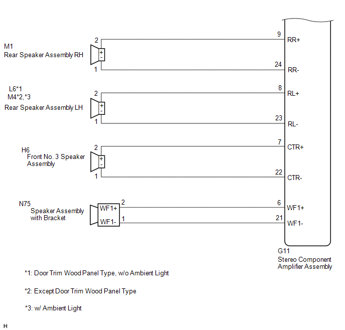
WIRING DIAGRAM
for 10 Speakers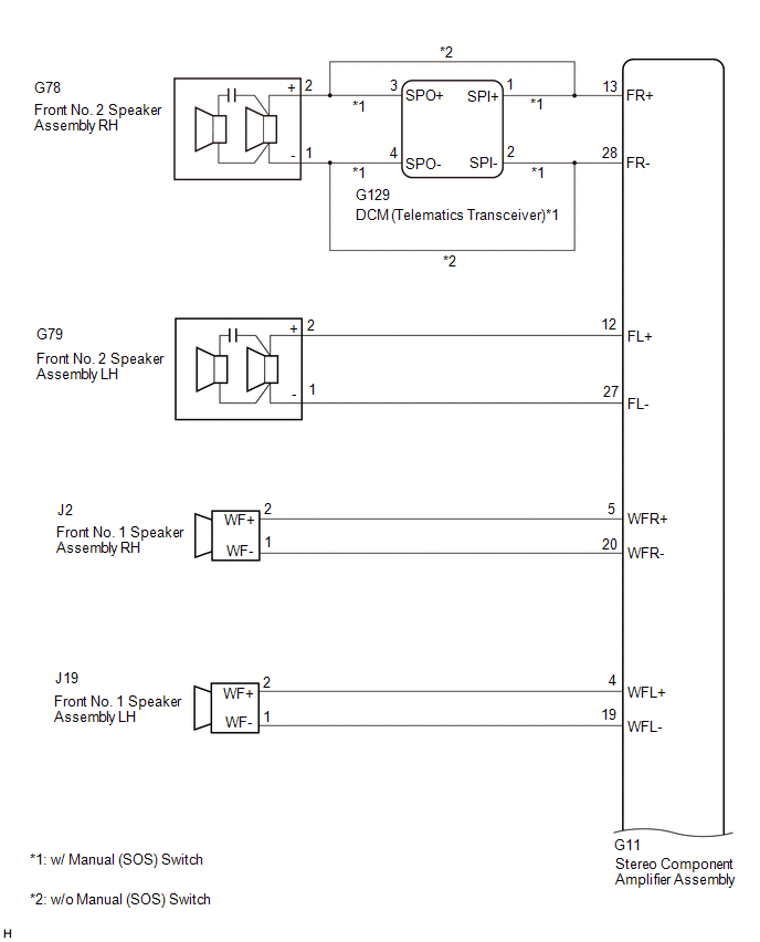
 for 17 Speakers
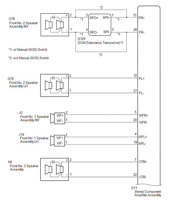
.png)
CAUTION / NOTICE / HINT
NOTICE:
-
Depending on the parts that are replaced during vehicle inspection or maintenance, performing initialization, registration or calibration may be needed. Refer to Precaution for Navigation System.
Click here
.gif)
-
Before replacing the DCM (telematics transceiver), refer to Registration
Click here
PROCEDURE
| 1. | CHECK MODEL |
(a) Choose the model to be inspected.
| Result | Proceed to |
|---|---|
| for 10 Speakers (w/ Manual (SOS) Switch) | A |
| for 10 Speakers (w/o Manual (SOS) Switch) | B |
| for 17 Speakers (w/ Manual (SOS) Switch) | C |
| for 17 Speakers (w/o Manual (SOS) Switch) | D |
| B | .gif) | GO TO STEP 5 |
| C | | GO TO STEP 11 |
| D | | GO TO STEP 14 |
|
.gif)
| 2. | CHECK HARNESS AND CONNECTOR (STEREO COMPONENT AMPLIFIER ASSEMBLY - BODY GROUND) |
(a) Disconnect the G11 stereo component amplifier assembly connector.
(b) Disconnect the G129 DCM (telematics transceiver) connector.
(c) Disconnect the G79 front No. 2 speaker assembly LH connector.
(d) Disconnect the J2 and J19 front No. 1 speaker assembly connectors.
(e) Disconnect the H6 front No. 3 speaker assembly connector.
(f) Disconnect the M1 and L6 rear speaker assembly connectors. (Door Trim Wood Panel Type, w/o Ambient Light)
(g) Disconnect the M1 and M4 rear speaker assembly connectors. (Except Door Trim Wood Panel Type)
(h) Disconnect the M1 and M4 rear speaker assembly connectors. (w/ Ambient Light)
(i) Disconnect the N75 speaker assembly with bracket connector.
(j) Measure the resistance according to the value(s) in the table below.
Standard Resistance:
| Tester Connection | Condition | Specified Condition |
|---|---|---|
| G11-13 (FR+) or G129-1 (SPI+) - Body ground | Always | 10 kΩ or higher |
| G11-28 (FR-) or G129-2 (SPI-) - Body ground | Always | 10 kΩ or higher |
| G11-12 (FL+) or G79-2 (+) - Body ground | Always | 10 kΩ or higher |
| G11-27 (FL-) or G79-1 (-) - Body ground | Always | 10 kΩ or higher |
| G11-5 (WFR+) or J2-2 (WF+) - Body ground | Always | 10 kΩ or higher |
| G11-20 (WFR-) or J2-1 (WF-) - Body ground | Always | 10 kΩ or higher |
| G11-4 (WFL+) or J19-2 (WF+) - Body ground | Always | 10 kΩ or higher |
| G11-19 (WFL-) or J19-1 (WF-) - Body ground | Always | 10 kΩ or higher |
| G11-7 (CTR+) or H6-2 (+) - Body ground | Always | 10 kΩ or higher |
| G11-22 (CTR-) or H6-1 (-) - Body ground | Always | 10 kΩ or higher |
| G11-9 (RR+) or M1-2 (+) - Body ground | Always | 10 kΩ or higher |
| G11-24 (RR-) or M1-1 (-) - Body ground | Always | 10 kΩ or higher |
| G11-8 (RL+) or L6-2 (+) - Body ground*1 | Always | 10 kΩ or higher |
| G11-23 (RL-) or L6-1 (-) - Body ground*1 | Always | 10 kΩ or higher |
| G11-8 (RL+) or M4-2 (+) - Body ground*2, *3 | Always | 10 kΩ or higher |
| G11-23 (RL-) or M4-1 (-) - Body ground*2, *3 | Always | 10 kΩ or higher |
| G11-6 (WF1+) or N75-2 (WF1+) - Body ground | Always | 10 kΩ or higher |
| G11-21 (WF1-) or N75-1 (WF1-) - Body ground | Always | 10 kΩ or higher |
- *1: Door Trim Wood Panel Type, w/o Ambient Light
- *2: Except Door Trim Wood Panel Type
- *3: w/ Ambient Light
| NG | | REPAIR OR REPLACE HARNESS OR CONNECTOR |
|
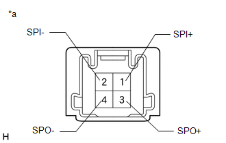
| 3. | CHECK HARNESS AND CONNECTOR (DCM (TELEMATICS TRANSCEIVER) - BODY GROUND) |
(a) Disconnect the G129 DCM (telematics transceiver) connector.
(b) Disconnect the G78 front No. 2 speaker assembly RH connector.
(c) Measure the resistance according to the value(s) in the table below.
Standard Resistance:
| Tester Connection | Condition | Specified Condition |
|---|---|---|
| G129-3 (SPO+) or G78-2 (+) - Body ground | Always | 10 kΩ or higher |
| G129-4 (SPO-) or G78-1 (-) - Body ground | Always | 10 kΩ or higher |
| NG | | REPAIR OR REPLACE HARNESS OR CONNECTOR |
|
| 4. | INSPECT DCM (TELEMATICS TRANSCEIVER) |
(a) Remove the DCM (telematics transceiver).
Click here
| (b) Measure the resistance according to the value(s) in the table below. Standard Resistance:
|
|
| OK | | GO TO STEP 6 |
| NG | | REPLACE DCM (TELEMATICS TRANSCEIVER) |
| 5. | CHECK HARNESS AND CONNECTOR (STEREO COMPONENT AMPLIFIER ASSEMBLY - BODY GROUND) |
(a) Disconnect the G11 stereo component amplifier assembly connector.
(b) Disconnect the G78 and G79 front No. 2 speaker assembly connectors.
(c) Disconnect the J2 and J19 front No. 1 speaker assembly connectors.
(d) Disconnect the H6 front No. 3 speaker assembly connector.
(e) Disconnect the M1 and M4 rear speaker assembly connectors.
(f) Disconnect the N75 speaker assembly with bracket connector.
(g) Measure the resistance according to the value(s) in the table below.
Standard Resistance:
| Tester Connection | Condition | Specified Condition |
|---|---|---|
| G11-13 (FR+) or G78-2 (+) - Body ground | Always | 10 kΩ or higher |
| G11-28 (FR-) or G78-1 (-) - Body ground | Always | 10 kΩ or higher |
| G11-12 (FL+) or G79-2 (+) - Body ground | Always | 10 kΩ or higher |
| G11-27 (FL-) or G79-1 (-) - Body ground | Always | 10 kΩ or higher |
| G11-5 (WFR+) or J2-2 (WF+) - Body ground | Always | 10 kΩ or higher |
| G11-20 (WFR-) or J2-1 (WF-) - Body ground | Always | 10 kΩ or higher |
| G11-4 (WFL+) or J19-2 (WF+) - Body ground | Always | 10 kΩ or higher |
| G11-19 (WFL-) or J19-1 (WF-) - Body ground | Always | 10 kΩ or higher |
| G11-7 (CTR+) or H6-2 (+) - Body ground | Always | 10 kΩ or higher |
| G11-22 (CTR-) or H6-1 (-) - Body ground | Always | 10 kΩ or higher |
| G11-9 (RR+) or M1-2 (+) - Body ground | Always | 10 kΩ or higher |
| G11-24 (RR-) or M1-1 (-) - Body ground | Always | 10 kΩ or higher |
| G11-8 (RL+) or M4-2 (+) - Body ground | Always | 10 kΩ or higher |
| G11-23 (RL-) or M4-1 (-) - Body ground | Always | 10 kΩ or higher |
| G11-6 (WF1+) or N75-2 (WF1+) - Body ground | Always | 10 kΩ or higher |
| G11-21 (WF1-) or N75-1 (WF1-) - Body ground | Always | 10 kΩ or higher |
| NG | | REPAIR OR REPLACE HARNESS OR CONNECTOR |
|
| 6. | INSPECT FRONT NO. 1 SPEAKER ASSEMBLY |
(a) Remove the front No. 1 speaker assembly.
Click here
(b) Inspect the front No. 1 speaker assembly.
Click here
| NG | | REPLACE FRONT NO. 1 SPEAKER ASSEMBLY |
|
| 7. | INSPECT REAR SPEAKER ASSEMBLY |
(a) Remove the rear speaker assembly.
Click here
(b) Inspect the rear speaker assembly.
Click here
| NG | | REPLACE REAR SPEAKER ASSEMBLY |
|
| 8. | INSPECT SPEAKER ASSEMBLY WITH BRACKET |
(a) Remove the speaker assembly with bracket.
Click here
(b) Inspect the speaker assembly with bracket.
Click here
| NG | | REPLACE SPEAKER ASSEMBLY WITH BRACKET |
|
| 9. | INSPECT FRONT NO. 3 SPEAKER ASSEMBLY |
(a) Remove the front No. 3 speaker assembly.
Click here
(b) Inspect the front No. 3 speaker assembly.
Click here
| NG | | REPLACE FRONT NO. 3 SPEAKER ASSEMBLY |
|
| 10. | REPLACE FRONT NO. 2 SPEAKER ASSEMBLY |
(a) Remove the front No. 2 speaker assembly.
Click here
(b) Inspect the front No. 2 speaker assembly.
Click here
(c) Clear the DTCs.
Body Electrical > Navigation System > Clear DTCs(d) Recheck for DTCs and check that no DTCs are output.
Body Electrical > Navigation System > Trouble CodesOK:
No DTCs are output.
| OK | | END |
| NG | | REPLACE STEREO COMPONENT AMPLIFIER ASSEMBLY |
| 11. | CHECK HARNESS AND CONNECTOR (STEREO COMPONENT AMPLIFIER ASSEMBLY - BODY GROUND) |
(a) Disconnect the G11 stereo component amplifier assembly connector.
(b) Disconnect the G129 DCM (telematics transceiver) connector.
(c) Disconnect the G79 front No. 2 speaker assembly LH connector.
(d) Disconnect the J2 and J19 front No. 1 speaker assembly connectors.
(e) Disconnect the H6 front No. 3 speaker assembly connector.
(f) Disconnect the J1 and J18 front No. 4 speaker assembly connectors.
(g) Disconnect the M1 and M4 rear speaker assembly connectors.
(h) Disconnect the N75 speaker assembly with bracket connector.
(i) Measure the resistance according to the value(s) in the table below.
Standard Resistance:
| Tester Connection | Condition | Specified Condition |
|---|---|---|
| G11-13 (FR+) or G129-1 (SPI+) - Body ground | Always | 10 kΩ or higher |
| G11-28 (FR-) or G129-2 (SPI-) - Body ground | Always | 10 kΩ or higher |
| G11-12 (FL+) or G79-2 (+) - Body ground | Always | 10 kΩ or higher |
| G11-27 (FL-) or G79-1 (-) - Body ground | Always | 10 kΩ or higher |
| G11-5 (WFR+) or J2-2 (WF+) - Body ground | Always | 10 kΩ or higher |
| G11-20 (WFR-) or J2-1 (WF-) - Body ground | Always | 10 kΩ or higher |
| G11-4 (WFL+) or J19-2 (WF+) - Body ground | Always | 10 kΩ or higher |
| G11-19 (WFL-) or J19-1 (WF-) - Body ground | Always | 10 kΩ or higher |
| G11-7 (CTR+) or H6-2 (+) - Body ground | Always | 10 kΩ or higher |
| G11-22 (CTR-) or H6-1 (-) - Body ground | Always | 10 kΩ or higher |
| G11-9 (RR+) or M1-2 (+) - Body ground | Always | 10 kΩ or higher |
| G11-24 (RR-) or M1-1 (-) - Body ground | Always | 10 kΩ or higher |
| G11-8 (RL+) or M4-2 (+) - Body ground | Always | 10 kΩ or higher |
| G11-23 (RL-) or M4-1 (-) - Body ground | Always | 10 kΩ or higher |
| G11-11 (TWR+) or J1-2 (+) - Body ground | Always | 10 kΩ or higher |
| G11-26 (TWR-) or J1-1 (-) - Body ground | Always | 10 kΩ or higher |
| G11-10 (TWL+) or J18-2 (+) - Body ground | Always | 10 kΩ or higher |
| G11-25 (TWL-) or J18-1 (-) - Body ground | Always | 10 kΩ or higher |
| G11-6 (WF1+) or N75-2 (WF1+) - Body ground | Always | 10 kΩ or higher |
| G11-21 (WF1-) or N75-1 (WF1-) - Body ground | Always | 10 kΩ or higher |
| NG | | REPAIR OR REPLACE HARNESS OR CONNECTOR |
|
| 12. | CHECK HARNESS AND CONNECTOR (DCM (TELEMATICS TRANSCEIVER) - BODY GROUND) |
(a) Disconnect the G129 DCM (telematics transceiver) connector.
(b) Disconnect the G78 front No. 2 speaker assembly RH connector.
(c) Measure the resistance according to the value(s) in the table below.
Standard Resistance:
| Tester Connection | Condition | Specified Condition |
|---|---|---|
| G129-3 (SPO+) or G78-2 (+) - Body ground | Always | 10 kΩ or higher |
| G129-4 (SPO-) or G78-1 (-) - Body ground | Always | 10 kΩ or higher |
| NG | | REPAIR OR REPLACE HARNESS OR CONNECTOR |
|
| 13. | INSPECT DCM (TELEMATICS TRANSCEIVER) |
(a) Remove the DCM (telematics transceiver).
Click here
| (b) Measure the resistance according to the value(s) in the table below. Standard Resistance:
|
|
| OK | | GO TO STEP 15 |
| NG | | REPLACE DCM (TELEMATICS TRANSCEIVER) |
| 14. | CHECK HARNESS AND CONNECTOR (STEREO COMPONENT AMPLIFIER ASSEMBLY - BODY GROUND) |
(a) Disconnect the G11 stereo component amplifier assembly connector.
(b) Disconnect the G78 and G79 front No. 2 speaker assembly connectors.
(c) Disconnect the J2 and J19 front No. 1 speaker assembly connectors.
(d) Disconnect the H6 front No. 3 speaker assembly connector.
(e) Disconnect the J1 and J18 front No. 4 speaker assembly connectors.
(f) Disconnect the M1 and M4 rear speaker assembly connectors.
(g) Disconnect the N75 speaker assembly with bracket connector.
(h) Measure the resistance according to the value(s) in the table below.
Standard Resistance:
| Tester Connection | Condition | Specified Condition |
|---|---|---|
| G11-13 (FR+) or G78-2 (+) - Body ground | Always | 10 kΩ or higher |
| G11-28 (FR-) or G78-1 (-) - Body ground | Always | 10 kΩ or higher |
| G11-12 (FL+) or G79-2 (+) - Body ground | Always | 10 kΩ or higher |
| G11-27 (FL-) or G79-1 (-) - Body ground | Always | 10 kΩ or higher |
| G11-5 (WFR+) or J2-2 (WF+) - Body ground | Always | 10 kΩ or higher |
| G11-20 (WFR-) or J2-1 (WF-) - Body ground | Always | 10 kΩ or higher |
| G11-4 (WFL+) or J19-2 (WF+) - Body ground | Always | 10 kΩ or higher |
| G11-19 (WFL-) or J19-1 (WF-) - Body ground | Always | 10 kΩ or higher |
| G11-7 (CTR+) or H6-2 (+) - Body ground | Always | 10 kΩ or higher |
| G11-22 (CTR-) or H6-1 (-) - Body ground | Always | 10 kΩ or higher |
| G11-9 (RR+) or M1-2 (+) - Body ground | Always | 10 kΩ or higher |
| G11-24 (RR-) or M1-1 (-) - Body ground | Always | 10 kΩ or higher |
| G11-8 (RL+) or M4-2 (+) - Body ground | Always | 10 kΩ or higher |
| G11-23 (RL-) or M4-1 (-) - Body ground | Always | 10 kΩ or higher |
| G11-11 (TWR+) or J1-2 (+) - Body ground | Always | 10 kΩ or higher |
| G11-26 (TWR-) or J1-1 (-) - Body ground | Always | 10 kΩ or higher |
| G11-10 (TWL+) or J18-2 (+) - Body ground | Always | 10 kΩ or higher |
| G11-25 (TWL-) or J18-1 (-) - Body ground | Always | 10 kΩ or higher |
| G11-6 (WF1+) or N75-2 (WF1+) - Body ground | Always | 10 kΩ or higher |
| G11-21 (WF1-) or N75-1 - (WF1-) Body ground | Always | 10 kΩ or higher |
| NG | | REPAIR OR REPLACE HARNESS OR CONNECTOR |
|
| 15. | INSPECT FRONT NO. 1 SPEAKER ASSEMBLY |
(a) Remove the front No. 1 speaker assembly.
Click here
(b) Inspect the front No. 1 speaker assembly.
Click here
| NG | | REPLACE FRONT NO. 1 SPEAKER ASSEMBLY |
|
| 16. | INSPECT SPEAKER ASSEMBLY WITH BRACKET |
(a) Remove the speaker assembly with bracket.
Click here
(b) Inspect the speaker assembly with bracket.
Click here
| NG | | REPLACE SPEAKER ASSEMBLY WITH BRACKET |
|
| 17. | REPLACE FRONT NO. 2 SPEAKER ASSEMBLY |
(a) Remove the front No. 2 speaker assembly.
Click here
(b) Inspect the front No. 2 speaker assembly.
Click here
(c) Clear the DTCs.
Body Electrical > Navigation System > Clear DTCs(d) Recheck for DTCs and check that no DTCs are output.
Body Electrical > Navigation System > Trouble CodesOK:
No DTCs are output.
| OK | | END |
|
| 18. | REPLACE FRONT NO. 3 SPEAKER ASSEMBLY |
(a) Remove the front No. 3 speaker assembly.
Click here
(b) Inspect the front No. 3 speaker assembly.
Click here
(c) Clear the DTCs.
Body Electrical > Navigation System > Clear DTCs(d) Recheck for DTCs and check that no DTCs are output.
Body Electrical > Navigation System > Trouble CodesOK:
No DTCs are output.
| OK | | END |
|
| 19. | REPLACE FRONT NO. 4 SPEAKER ASSEMBLY |
(a) Remove the front No. 4 speaker assembly.
Click here
(b) Inspect the front No. 4 speaker assembly.
Click here
(c) Clear the DTCs.
Body Electrical > Navigation System > Clear DTCs(d) Recheck for DTCs and check that no DTCs are output.
Body Electrical > Navigation System > Trouble CodesOK:
No DTCs are output.
| OK | | END |
|
| 20. | REPLACE REAR SPEAKER ASSEMBLY |
(a) Remove the rear speaker assembly.
Click here
(b) Inspect the rear speaker assembly.
Click here
(c) Clear the DTCs.
Body Electrical > Navigation System > Clear DTCs(d) Recheck for DTCs and check that no DTCs are output.
Body Electrical > Navigation System > Trouble CodesOK:
No DTCs are output.
| OK | | END |
| NG | | REPLACE STEREO COMPONENT AMPLIFIER ASSEMBLY |
READ NEXT:
 MOST Communication Malfunction (B15D0)
DESCRIPTION Navigation system components communicate with each other via MOST communication. If a line short or short to ground occurs in a MOST communication line, communication will not be possible
Stereo Component Amplifier Disconnected (B15D3)
DESCRIPTION The radio receiver assembly and stereo component amplifier assembly are connected via MOST communication lines. When a MOST communication error occurs between the radio receiver assembly a
Operation Panel Disconnected (B15D9)
DESCRIPTION The multi-display assembly and air conditioning control assembly are connected by AVC-LAN communication lines. This DTC is stored when an AVC-LAN communication error occurs between the mul
SEE MORE:
Lost Communication with Drive Motor Control Module "A" Missing Message (U011087)
MONITOR DESCRIPTION The ECM and inverter with converter assembly (MG ECU) send and receive signals via CAN communication. If a communication error occurs between the ECM and inverter with converter assembly, the ECM illuminates the MIL and stores this DTC. DTC No. Detection Item DTC Detection
Removal
REMOVAL CAUTION / NOTICE / HINT The necessary procedures (adjustment, calibration, initialization or registration) that must be performed after parts are removed and installed, or replaced during fuel pump assembly removal/installation are shown below. Necessary Procedures After Parts Removed/Instal
