Lexus ES: Installation
INSTALLATION
PROCEDURE
1. INSTALL TRANSMISSION FLOOR SHIFT ASSEMBLY
(a) Engage the clamp to connect the wire harness to the transmission floor shift assembly.
(b) Connect the shift lock control ECU connector.
(c) Engage the clamp to connect the wire harness to the transmission floor shift assembly.
(d) Connect the transmission control switch connector.
(e) Install the clip to the No. 1 console box duct.
(f) Temporarily install the transmission floor shift assembly to the vehicle body with the 4 bolts.
| (g) Tighten the 4 bolts in the order shown in the illustration. Torque: 12 N·m {122 kgf·cm, 9 ft·lbf} |
|
.png)
2. CONNECT TRANSMISSION CONTROL CABLE ASSEMBLY
NOTICE:
Before connecting the transmission control cable assembly, check that the shift lever is in N.
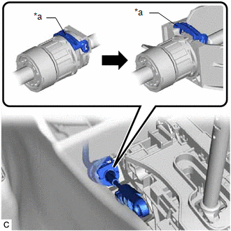
| (a) Slide the slider of the transmission control cable assembly in the direction indicated by the arrow in the illustration and pull the lock piece outward. |
|
.png)
| (b) Turn the lock nut of the transmission control cable assembly counterclockwise. While holding the lock nut, push in the stopper. |
|

| (c) Connect the transmission control cable assembly to the transmission floor shift assembly. NOTICE: After installation, check that the outer part of the stopper is as shown in the illustration. |
|
| (d) Connect the transmission control cable assembly to the transmission floor shift assembly. NOTICE:
|
|
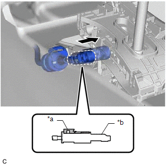
| (e) Push the lock piece into the adjuster case. NOTICE:
|
|
.png)
(f) After adjusting the shift lever position, check the position and operation of the shift lever. If there is a problem, adjust the shift lever position again.
3. INSTALL CONSOLE BOX ASSEMBLY
Click here .gif)
4. INSTALL SHIFT LEVER KNOB SUB-ASSEMBLY
Click here
5. INSTALL SHIFT LOCK RELEASE BUTTON COVER
| (a) Engage the 2 claws to install the shift lock release button cover to the upper console panel sub-assembly. |
|
.png)
6. INSPECT SHIFT LEVER POSITION
Click here
7. ADJUST SHIFT LEVER POSITION
Click here
READ NEXT:
 On-vehicle Inspection
ON-VEHICLE INSPECTION PROCEDURE 1. SECURE VEHICLE (a) Fully apply the parking brake and chock a wheel. CAUTION:
Make sure to apply the parking brake and chock a wheel before performing this procedu
Reassembly
REASSEMBLY PROCEDURE 1. INSTALL LOWER POSITION INDICATOR HOUSING (a) Engage the 4 claws and 2 guides to install the lower position indicator housing to the shift lock control unit assembly. NOTICE:
Removal
REMOVAL PROCEDURE 1. SECURE VEHICLE (a) Fully apply the parking brake and chock a wheel. CAUTION:
Make sure to apply the parking brake and chock a wheel before performing this procedure.
If the v
SEE MORE:
Customize Parameters
CUSTOMIZE PARAMETERS CUSTOMIZE LUGGAGE COMPARTMENT DOOR OPENER SYSTEM NOTICE:
When the customer requests a change in a function, first make sure that the function can be customized.
Be sure to make a note of the current settings before customizing.
When troubleshooting a function, first make
Components
COMPONENTS ILLUSTRATION *1 ENGINE WIRE *2 NO. 2 SURGE TANK STAY *3 EARTH WIRE - - Tightening torque for "Major areas involving basic vehicle performance such as moving/turning/stopping": N*m (kgf*cm, ft.*lbf) N*m (kgf*cm, ft.*lbf): Specified torque ILLUSTRATION
