Lexus ES: Components
COMPONENTS
ILLUSTRATION
.png)
| *1 | BATTERY CLAMP SUB-ASSEMBLY | - | - |
.png) | N*m (kgf*cm, ft.*lbf): Specified torque | - | - |
ILLUSTRATION
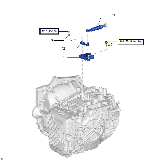
| *1 | TRANSMISSION CONTROL CABLE ASSEMBLY | *2 | TRANSMISSION CONTROL SHAFT LEVER |
| *3 | PARK/NEUTRAL POSITION SWITCH ASSEMBLY | *4 | WASHER |
.png) | Tightening torque for "Major areas involving basic vehicle performance such as moving/turning/stopping": N*m (kgf*cm, ft.*lbf) | - | - |
READ NEXT:
 Inspection
INSPECTION PROCEDURE 1. INSPECT PARK/NEUTRAL POSITION SWITCH ASSEMBLY (a) Measure the resistance according to the value(s) in the table below when the transmission control shaft lever is moved to e
Installation
INSTALLATION PROCEDURE 1. INSTALL PARK/NEUTRAL POSITION SWITCH ASSEMBLY (a) Temporarily install the park/neutral position switch assembly to the automatic transaxle case sub-assembly with the 2 bolts.
On-vehicle Inspection
ON-VEHICLE INSPECTION PROCEDURE 1. SECURE VEHICLE (a) Fully apply the parking brake and chock a wheel. CAUTION:
Make sure to apply the parking brake and chock a wheel before performing this procedu
SEE MORE:
Installation
INSTALLATION PROCEDURE 1. INSTALL REAR SPOILER SUB-ASSEMBLY HINT: When installing a new rear spoiler sub-assembly, heat the luggage compartment door panel and rear spoiler sub-assembly using a heat light. Heating Temperature Item Temperature Luggage Compartment Door Panel 40 to 60°C (104
Lost Communication with ECM / PCM "A" (U0100,U0125,U0126,U0129,U0142,U0293)
DESCRIPTION These DTCs are stored if there is a malfunction in the CAN communication system connected to the blind spot monitor sensor. HINT: If CAN communication system DTCs are stored, they may also be stored for other systems. Blind Spot Monitor Master DTC No. Detection Item DTC Detection
© 2016-2026 Copyright www.lexguide.net
