Lexus ES: Installation
INSTALLATION
PROCEDURE
1. INSTALL STOP LIGHT SWITCH ASSEMBLY
(a) Insert the stop light switch assembly until the threaded sleeve hits the pedal as shown in the illustration.
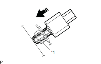
| *1 | Stop Light Switch Mounting Adjuster |
.png) | Insert in this Direction |
NOTICE:
When inserting the stop light switch assembly, support the pedal from behind so that the pedal is not pushed in.
(b) Turn the stop light switch assembly 1/4 turn clockwise as shown in the illustration to install it.
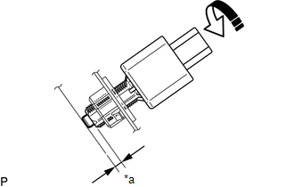
| *a | Protrusion of the Plunger |
| | Turn in this Direction |
Torque:
1.5 N·m {15 kgf·cm, 13 in·lbf}
or less
(c) Connect the connector.
(d) Check the protrusion of the plunger.
Protrusion of the Plunger| Area | Measurement |
|---|---|
| a | 0.5 to 2.6 mm (0.0197 to 0.102 in.) |
(e) If the protrusion is not as specified, recheck the stop light switch assembly installation and perform brake pedal adjustment if necessary.
for Gasoline Model:
Click here .gif)
for HV Model:
Click here
NOTICE:
Do not depress or support the brake pedal.
2. INSTALL NO. 1 INSTRUMENT PANEL UNDER COVER SUB-ASSEMBLY
Click here
READ NEXT:
 Components
COMPONENTS ILLUSTRATION *A for Power Tilt and Power Telescopic Steering Column - - *1 STEERING WHEEL SWITCH HOUSING *2 TILT AND TELESCOPIC SWITCH *3 TURN SIGNAL SWITCH *4
Removal
REMOVAL CAUTION / NOTICE / HINT The necessary procedures (adjustment, calibration, initialization, or registration) that must be performed after parts are removed, installed, or replaced during the st
SEE MORE:
Headlight ECU RH Communication Stop Mode
DESCRIPTION Detection Item Symptom Trouble Area Headlight ECU RH Communication Stop Mode Any of the following conditions are met:
Communication stop for "HL AutoLeveling/AFS/AHS (Sub)" is indicated on the "Communication Bus Check" screen of the Techstream.
Click here
Communicat
Removal
REMOVAL CAUTION / NOTICE / HINT The necessary procedures (adjustment, calibration, initialization or registration) that must be performed after parts are removed and installed, or replaced during battery voltage sensor removal/installation are shown below. Necessary Procedures After Parts Removed/In
