Lexus ES: Installation
INSTALLATION
PROCEDURE
1. INSTALL PARK/NEUTRAL POSITION SWITCH ASSEMBLY
(a) Temporarily install the park/neutral position switch assembly to the automatic transaxle case sub-assembly with the 2 bolts.
NOTICE:
Before installing the park/neutral position switch assembly, remove any dirt or rust on the manual valve lever shaft sub-assembly. Be sure to install the park/neutral position switch assembly straight along the manual valve lever shaft sub-assembly while being careful not to deform the plate spring that supports the manual valve lever shaft sub-assembly. If the plate spring is deformed, the park/neutral position switch assembly cannot be installed correctly.
(b) Temporarily install the transmission control shaft lever to the park/neutral position switch assembly.
| (c) Turn the transmission control shaft lever clockwise until it stops, then turn it counterclockwise 2 notches. |
|
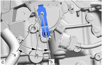
(d) Remove the transmission control shaft lever from the park/neutral position switch assembly.
| (e) Align the protrusion with the neutral basic line. |
|
.png)
(f) Hold the park/neutral position switch assembly in that position and tighten the 2 bolts.
Torque:
5.4 N·m {55 kgf·cm, 48 in·lbf}
(g) Install the transmission control shaft lever to the manual valve lever shaft sub-assembly with the washer and nut.
Torque:
12.7 N·m {130 kgf·cm, 9 ft·lbf}
(h) Connect the park/neutral position switch assembly connector.
2. CONNECT TRANSMISSION CONTROL CABLE ASSEMBLY
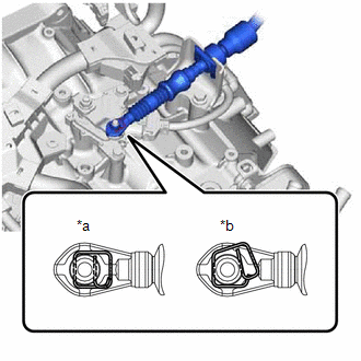
| (a) Connect the transmission control cable assembly to the transmission control shaft lever as shown in the illustration. NOTICE: Before connecting the transmission control cable assembly, check that the park/neutral position switch assembly and shift lever are in N. |
|
3. INSTALL BATTERY CLAMP SUB-ASSEMBLY
Click here .gif)
4. INSTALL ECM
Click here
5. INSTALL BATTERY
Click here
6. INSPECT PARK/NEUTRAL POSITION SWITCH ASSEMBLY OPERATION
Click here
7. INSPECT SHIFT LEVER POSITION
Click here
8. ADJUST SHIFT LEVER POSITION
Click here
READ NEXT:
 On-vehicle Inspection
ON-VEHICLE INSPECTION PROCEDURE 1. SECURE VEHICLE (a) Fully apply the parking brake and chock a wheel. CAUTION:
Make sure to apply the parking brake and chock a wheel before performing this procedu
Shift Lever Knob
ComponentsCOMPONENTS ILLUSTRATION *1 SHIFT LEVER KNOB SUB-ASSEMBLY - - InstallationINSTALLATION PROCEDURE 1. INSTALL SHIFT LEVER KNOB SUB-ASSEMBLY (a) Install the shift lever knob su
SEE MORE:
How To Proceed With Troubleshooting
CAUTION / NOTICE / HINT HINT:
Use the following procedure to troubleshoot the windshield deicer system.
*: Use the Techstream.
PROCEDURE 1. VEHICLE BROUGHT TO WORKSHOP
NEXT 2. CUSTOMER PROBLEM ANALYSIS HINT:
In troubleshooting, confirm that the problem s
Terminals Of Ecu
TERMINALS OF ECU CHECK SLIDING ROOF ECU (SLIDING ROOF DRIVE GEAR SUB-ASSEMBLY) (a) Disconnect the P22 sliding roof ECU (sliding roof drive gear sub-assembly) connector. (b) Measure the resistance and voltage according to the value(s) in the table below. HINT: Measure the values on the wire harness
