Lexus ES: Components
COMPONENTS
ILLUSTRATION
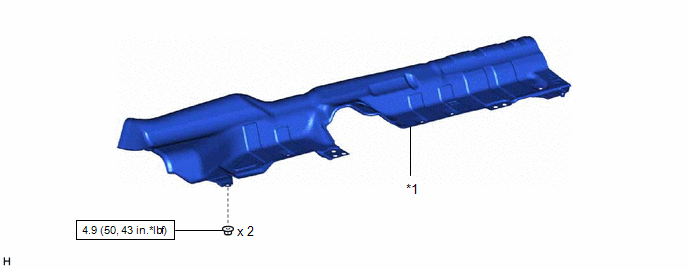
| *1 | FRONT LOWER NO. 1 FLOOR HEAT INSULATOR | - | - |
.png) | N*m (kgf*cm, ft.*lbf): Specified torque | - | - |
ILLUSTRATION
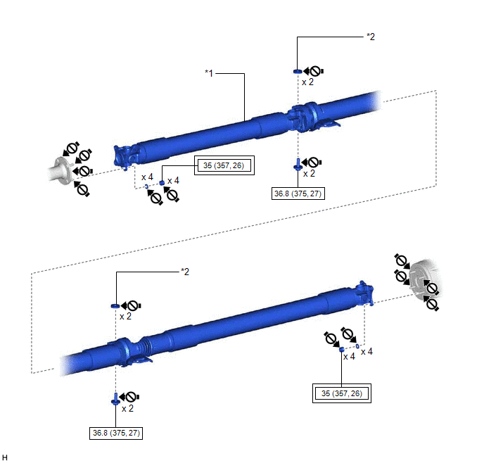
| *1 | PROPELLER WITH CENTER BEARING SHAFT ASSEMBLY | *2 | CENTER NO. 2 SUPPORT BEARING WASHER |
.png) | Tightening torque for "Major areas involving basic vehicle performance such as moving/turning/stopping": N*m (kgf*cm, ft.*lbf) | | N*m (kgf*cm, ft.*lbf): Specified torque |
.png) | Do not apply lubricants | - | - |
READ NEXT:
 Inspection
INSPECTION PROCEDURE 1. INSPECT PROPELLER WITH CENTER BEARING SHAFT ASSEMBLY (a) Using a dial indicator, measure the runout of the rear propeller shaft assembly (for front side). Maximum Runout: 0
Installation
INSTALLATION PROCEDURE 1. TEMPORARILY TIGHTEN PROPELLER WITH CENTER BEARING SHAFT ASSEMBLY (a) When reusing a propeller with center bearing shaft assembly and rear differential carrier assembly: (1
Removal
REMOVAL CAUTION / NOTICE / HINT The necessary procedures (adjustment, calibration, initialization, or registration) that must be performed after parts are removed and installed, or replaced during pro
SEE MORE:
Disposal
DISPOSAL PROCEDURE 1. DISPOSE OF HOOD SUPPORT ASSEMBLY (a) Secure the hood support assembly horizontally in a vise with the piston rod pulled out. (b) Wearing safety glasses, gradually cut a part within the area (a) shown in the illustration using a metal saw to release the gas. Specification:
Dtc Check / Clear
DTC CHECK / CLEAR CHECK FOR DTC (MAIN BODY) (a) Connect the Techstream to the DLC3. (b) Turn the engine switch on (IG). (c) Turn the Techstream on. (d) Enter the following menus: Body Electrical / Main Body / Trouble Codes. Body Electrical > Main Body > Trouble Codes (e) Check for DTCs. CHECK
© 2016-2026 Copyright www.lexguide.net
