Lexus ES: Components
COMPONENTS
ILLUSTRATION
.png)
| *1 | FRONT CENTER UPPER SUSPENSION BRACE SUB-ASSEMBLY | - | - |
.png) | Tightening torque for "Major areas involving basic vehicle performance such as moving/turning/stopping": N*m (kgf*cm, ft.*lbf) | .png) | N*m (kgf*cm, ft.*lbf): Specified torque |
| *T1 | Bolt color black: 8.0 N*m (82 kgf*cm, 71 in.*lbf) Bolt color silver: 8.9 N*m (91 kgf*cm, 79 in.*lbf) | - | - |
ILLUSTRATION
.png)
| *1 | NO. 1 INSTRUMENT PANEL UNDER COVER SUB-ASSEMBLY | - | - |
ILLUSTRATION
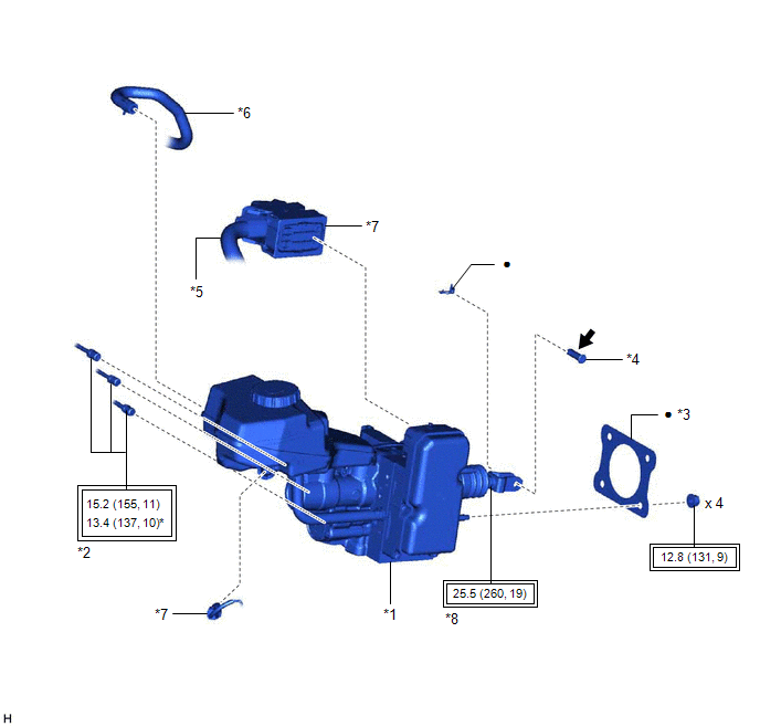
| *1 | BRAKE BOOSTER WITH MASTER CYLINDER ASSEMBLY | *2 | BRAKE LINE |
| *3 | BRAKE MASTER CYLINDER GASKET | *4 | BRAKE PEDAL LINK PIN |
| *5 | ENGINE ROOM MAIN WIRE | *6 | NO. 1 BRAKE ACTUATOR HOSE |
| *7 | CONNECTOR | *8 | LOCK NUT |
| | Tightening torque for "Major areas involving basic vehicle performance such as moving/turning/stopping": N*m (kgf*cm, ft.*lbf) | * | For use with a union nut wrench |
| ● | Non-reusable part | .png) | Lithium soap base glycol grease |
ILLUSTRATION
.png)
| *1 | BRAKE PEDAL STROKE SENSOR ASSEMBLY | *2 | BRAKE PEDAL SUPPORT ASSEMBLY |
| | N*m (kgf*cm, ft.*lbf): Specified torque | - | - |
ILLUSTRATION
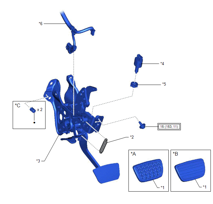
| *A | w/ Rubber Pad | *B | w/ Aluminum Pad |
| *C | for TMC Made | - | - |
| *1 | BRAKE PEDAL PAD | *2 | BRAKE PEDAL RETURN SPRING |
| *3 | BRAKE PEDAL SUPPORT ASSEMBLY | *4 | STOP LIGHT SWITCH ASSEMBLY |
| *5 | STOP LIGHT SWITCH MOUNTING ADJUSTER | *6 | WIRE HARNESS |
| | Tightening torque for "Major areas involving basic vehicle performance such as moving/turning/stopping": N*m (kgf*cm, ft.*lbf) | ● | Non-reusable part |
READ NEXT:
 Installation
INSTALLATION PROCEDURE 1. INSTALL BRAKE PEDAL PAD (a) Install the brake pedal pad to the brake pedal support assembly. HINT: Installation is easier after applying a small amount of soapy water. 2. INS
Removal
REMOVAL CAUTION / NOTICE / HINT The necessary procedures (adjustment, calibration, initialization, or registration) that must be performed after parts are removed, installed, or replaced during brake
SEE MORE:
Replacement
REPLACEMENT CAUTION / NOTICE / HINT The necessary procedures (adjustment, calibration, initialization, or registration) that must be performed after parts are removed and installed, or replaced during input shaft type T oil seal removal/installation are shown below. Necessary Procedure After Parts R
Precaution
PRECAUTION PRECAUTION FOR DISCONNECTING CABLE FROM NEGATIVE AUXILIARY BATTERY TERMINAL NOTICE: When disconnecting the cable from the negative (-) auxiliary battery terminal, initialize the following systems after the cable is reconnected. System Name See Procedure Lane Control System (for H
