Lexus ES: Installation
INSTALLATION
PROCEDURE
1. INSTALL BRAKE PEDAL PAD
(a) Install the brake pedal pad to the brake pedal support assembly.
HINT:
Installation is easier after applying a small amount of soapy water.
2. INSTALL STOP LIGHT SWITCH MOUNTING ADJUSTER
(a) Engage the 2 claws to install the stop light switch mounting adjuster.
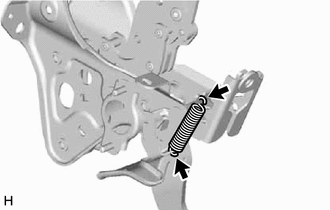
3. INSTALL BRAKE PEDAL RETURN SPRING
| (a) Install the brake pedal return spring to the brake pedal support assembly. NOTICE: Attach the bottom part of the brake pedal return spring first, making sure that the open part of the hook is facing the front of the vehicle. Attach the top part of the brake pedal return spring second, making sure that the open part of the hook is facing the rear of the vehicle. |
|
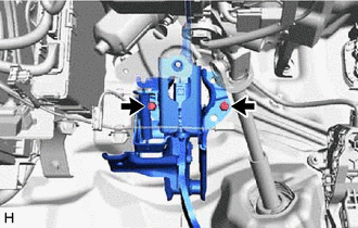
4. INSTALL BRAKE PEDAL SUPPORT ASSEMBLY
(a) Install the brake pedal support assembly while avoiding the stud bolts of the brake booster support base.
NOTICE:
Be careful not to deform the bracket of the instrument panel reinforcement assembly.
| (b) for TMC Made: Install 2 new clips. |
|
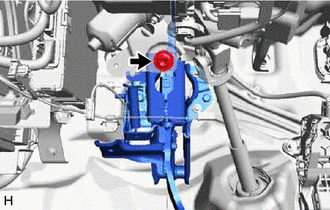
| (c) Install the brake pedal support assembly to the instrument panel reinforcement assembly with the bolt. Torque: 15 N·m {153 kgf·cm, 11 ft·lbf} |
|
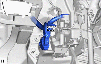
| (d) Engage the clamp to install the wire harness to the brake pedal support assembly. |
|
5. INSTALL BRAKE MASTER CYLINDER GASKET
Click here .gif)
6. INSTALL BRAKE BOOSTER WITH MASTER CYLINDER ASSEMBLY
Click here
7. INSTALL BRAKE PEDAL LINK PIN
Click here
8. INSTALL STOP LIGHT SWITCH ASSEMBLY
Click here
9. INSTALL BRAKE PEDAL STROKE SENSOR ASSEMBLY
Click here
10. CONNECT BRAKE LINE
Click here
11. CONNECT NO. 1 BRAKE ACTUATOR HOSE
Click here
12. CONNECT ENGINE ROOM MAIN WIRE
Click here
13. BLEED NO. 1 BRAKE ACTUATOR TUBE
Click here
14. CONNECT BRAKE BOOSTER PUMP CONNECTOR
Click here
HINT:
Perform this operation only when the accumulator pressure zero down operation could not be performed using the Techstream.
15. FILL RESERVOIR WITH BRAKE FLUID
16. CONNECT CABLE TO NEGATIVE AUXILIARY BATTERY TERMINAL
Click here
17. BLEED BRAKE SYSTEM
Click here
18. INSPECT AND ADJUST BRAKE PEDAL
Click here
19. INSTALL NO. 1 INSTRUMENT PANEL UNDER COVER SUB-ASSEMBLY
Click here
20. INSTALL FRONT CENTER UPPER SUSPENSION BRACE SUB-ASSEMBLY
Click here
21. INSTALL COWL TOP VENTILATOR LOUVER SUB-ASSEMBLY
Click here
READ NEXT:
 Removal
REMOVAL CAUTION / NOTICE / HINT The necessary procedures (adjustment, calibration, initialization, or registration) that must be performed after parts are removed, installed, or replaced during brake
Precaution
PRECAUTION NOTICE:
This vehicle is equipped with an SRS (Supplemental Restraint System). Failure to carry out service operations in the correct sequence could cause the SRS to unexpectedly deploy d
SEE MORE:
Freeze Frame Data
FREEZE FRAME DATA FREEZE FRAME DATA HINT: The hybrid vehicle control ECU records vehicle and driving condition information as freeze frame data the moment a DTC is stored. It can be used for estimating or duplicating the vehicle conditions that were present when the malfunction occurred. (a) Connect
Components
COMPONENTS ILLUSTRATION *1 LUGGAGE COMPARTMENT FLOOR MAT *2 SPARE WHEEL COVER TRAY ILLUSTRATION *1 REAR FLOOR FINISH PLATE *2 LUGGAGE HOLD BELT STRIKER ASSEMBLY ILLUSTRATION *1 LUGGAGE COMPARTMENT DOOR COVER *2 LUGGAGE LOCK CONTROL CABLE PLATE ILLUSTRATION
