Lexus ES: Removal
REMOVAL
CAUTION / NOTICE / HINT
The necessary procedures (adjustment, calibration, initialization, or registration) that must be performed after parts are removed, installed, or replaced during brake pedal support assembly removal/installation are shown below.
Necessary Procedures After Parts Removed/Installed/Replaced| Replaced Part or Performed Procedure | Necessary Procedure | Effect/Inoperative Function when Necessary Procedure not Performed | Link |
|---|---|---|---|
|
*: When performing learning using the Techstream.
Click here | |||
| Auxiliary battery terminal is disconnected/reconnected | Perform steering sensor zero point calibration | Lane Control System | |
| Pre-collision System | |||
| Parking Support Brake System* | |||
| Lighting System | |||
| Memorize steering angle neutral point | Parking Assist Monitor System | | |
| Panoramic View Monitor System | | ||
| Initialize power trunk lid system | Power Trunk Lid System | | |
| Replacement of brake pedal support assembly |
|
| for Initialization: for Calibration: |
NOTICE:
- After the power switch is turned off, the radio receiver assembly records various types of memory and settings. As a result, after turning the power switch off, make sure to wait at least 85 seconds before disconnecting the cable from the negative (-) auxiliary battery terminal. (for Audio and Visual System)
- After the power switch is turned off, the radio receiver assembly records various types of memory and settings. As a result, after turning the power switch off, make sure to wait at least 85 seconds before disconnecting the cable from the negative (-) auxiliary battery terminal. (for Navigation System)
CAUTION / NOTICE / HINT
NOTICE:
While the auxiliary battery is connected, even if the power switch is off, the brake control system activates when the brake pedal is depressed or any door courtesy switch turns on. Therefore, when servicing the brake system components, do not operate the brake pedal or open/close the doors while the auxiliary battery is connected.
PROCEDURE
1. REMOVE BRAKE BOOSTER WITH MASTER CYLINDER ASSEMBLY
Click here .gif)
2. REMOVE BRAKE PEDAL STROKE SENSOR ASSEMBLY
Click here
3. REMOVE STOP LIGHT SWITCH ASSEMBLY
Click here
4. REMOVE BRAKE PEDAL SUPPORT ASSEMBLY
| (a) Disengage the clamp to separate the wire harness from the brake pedal support assembly. |
|
.png)
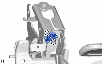
| (b) Remove the bolt and separate the brake pedal support assembly from the instrument panel reinforcement assembly. |
|
.png)
| (c) for TMC Made: Remove the 2 clips. |
|
.png)
(d) Remove the brake pedal support assembly while avoiding the stud bolts of the brake booster support base.
NOTICE:
Be careful not to deform the bracket of the instrument panel reinforcement assembly.
5. REMOVE BRAKE PEDAL RETURN SPRING
| (a) Remove the brake pedal return spring from the brake pedal support assembly. |
|
.png)
6. REMOVE STOP LIGHT SWITCH MOUNTING ADJUSTER
| (a) Disengage the 2 claws and remove the stop light switch mounting adjuster. |
|
7. REMOVE BRAKE PEDAL PAD
(a) Remove the brake pedal pad from the brake pedal support assembly.
READ NEXT:
 Precaution
PRECAUTION NOTICE:
This vehicle is equipped with an SRS (Supplemental Restraint System). Failure to carry out service operations in the correct sequence could cause the SRS to unexpectedly deploy d
Problem Symptoms Table
PROBLEM SYMPTOMS TABLE HINT: Use the table below to help determine the cause of problem symptoms. If multiple suspected areas are listed, the potential causes of the symptoms are listed in order of pr
SEE MORE:
Driver Side Power Window Auto Up / Down Function does not Operate with Power Window Master Switch
DESCRIPTION If the manual up and down functions operate normally but the auto up and down functions do not, the power window control system may be in fail-safe mode. If power window initialization has not been performed, the auto up and down functions will not operate. Click here WIRING DIAGRAM C
Air Bag Circuit (C147D)
DESCRIPTION The skid control ECU (brake booster with master cylinder assembly) receives the secondary collision brake control request signal from the airbag ECU assembly. DTC No. Detection Item INF Code DTC Detection Condition Trouble Area MIL Note C147D Air Bag Circuit 451
