Lexus ES: Components
COMPONENTS
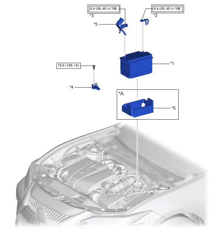
ILLUSTRATION
|
*A |
w/ Battery Insulator |
- |
- |
|
*1 |
BATTERY |
*2 |
NEGATIVE BATTERY TERMINAL |
|
*3 |
POSITIVE BATTERY TERMINAL |
*4 |
NO. 2 BATTERY CLAMP |
|
*5 |
BATTERY TERMINAL CAP |
*6 |
BATTERY INSULATOR |
.png) |
Tightening torque for "Major areas involving basic vehicle performance such as moving/turning/stopping": N*m (kgf*cm, ft.*lbf) |
.png) |
N*m (kgf*cm, ft.*lbf): Specified torque |
READ NEXT:
 Removal
REMOVAL
CAUTION / NOTICE / HINT
The necessary procedures (adjustment, calibration, initialization or registration)
that must be performed after parts are removed and installed, or replaced battery
Installation
INSTALLATION
PROCEDURE
1. INSTALL BATTERY
(a) w/ Battery Insulator
(1) Install the battery insulator to the battery.
(b) Install the battery to the vehicle.
(c) Install the No. 2 battery clamp t
2gr-fks Coolant
Components
COMPONENTS
ILLUSTRATION
*1
RADIATOR CAP SUB-ASSEMBLY
*2
RADIATOR DRAIN COCK PLUG
*3
NO. 1 ENGINE UNDER COVER
SEE MORE:
Data List / Active Test
DATA LIST / ACTIVE TEST NOTICE: In the table below, the values listed under "Normal Condition" are reference values. Do not depend solely on these reference values when deciding whether a part is faulty or not. The actual values may differ from the values listed in the chart under "Reference Value"
Inspection
INSPECTION PROCEDURE 1. INSPECT REAR STABILIZER LINK ASSEMBLY (a) Inspect the turning torque of the ball joint. (1) Secure the rear stabilizer link assembly in a vise using aluminum plates. NOTICE: Do not overtighten the vise. (2) Install the nut to the rear stabilizer link assembly stud. (3) Move
© 2016-2026 Copyright www.lexguide.net
