Lexus ES: Removal
REMOVAL
CAUTION / NOTICE / HINT
The necessary procedures (adjustment, calibration, initialization or registration) that must be performed after parts are removed and installed, or replaced battery removal/installation are shown below.
Necessary Procedures After Parts Removed/Installed/Replaced|
Replaced Part or Performed Procedure |
Necessary Procedure |
Effect/Inoperative Function when Necessary Procedure not Performed |
Link |
|---|---|---|---|
| *: When performing learning using the Techstream.
Click here |
|||
|
Battery terminal is disconnected/reconnected |
Perform steering sensor zero point calibration |
Lane Control System |
|
|
Pre-collision system |
|||
|
Parking Support Brake System* |
|||
|
Lighting System |
|||
|
Memorize steering angle neutral point |
Parking Assist Monitor System |
|
|
|
Panoramic View Monitor System |
|
||
|
Initialize power trunk lid system |
Power Trunk Lid System (for Gasoline Model) |
|
|
.gif)
NOTICE:
- After the engine switch is turned off, the radio receiver assembly records various types of memory and settings. As a result, after turning the engine switch off, make sure to wait at least 85 seconds before disconnecting the cable from the negative (-) battery terminal. (for Audio and Visual System)
- After the engine switch is turned off, the radio receiver assembly records various types of memory and settings. As a result, after turning the engine switch off, make sure to wait at least 85 seconds before disconnecting the cable from the negative (-) battery terminal. (for Navigation System)
- When replacing the battery, use a new battery of the same dimensions and same capacity or more from the same class at a 20-hour rate.
PROCEDURE
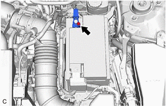
1. DISCONNECT CABLE FROM NEGATIVE BATTERY TERMINAL
|
(a) Loosen the nut, and disconnect the cable from the negative (-) battery terminal. NOTICE: When disconnecting the cable, some systems need to be initialized after the cable is reconnected. Click here |
|
2. REMOVE BATTERY
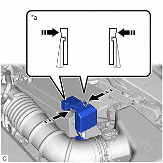
(a) Disengage the 2 claws and remove the battery terminal cap from the positive (+) battery terminal in the order shown in the illustration.
|
*a |
Side View of Claws |
 |
Push Battery Terminal Cap Here |
 |
Push |
|
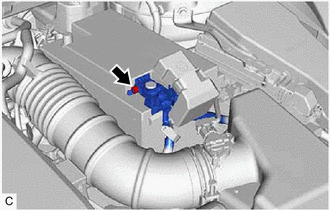
(b) Loosen the nut and disconnect the cable from the positive (+) battery terminal. |
|
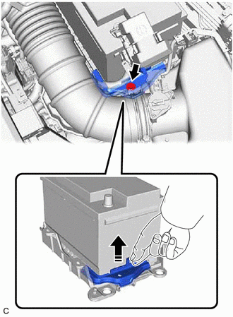
(c) Remove the bolt and No. 2 battery clamp from the battery clamp sub-assembly.
|
|
Remove in this Direction |
(d) Remove the battery from the vehicle.
READ NEXT:
 Installation
INSTALLATION
PROCEDURE
1. INSTALL BATTERY
(a) w/ Battery Insulator
(1) Install the battery insulator to the battery.
(b) Install the battery to the vehicle.
(c) Install the No. 2 battery clamp t
2gr-fks Coolant
Components
COMPONENTS
ILLUSTRATION
*1
RADIATOR CAP SUB-ASSEMBLY
*2
RADIATOR DRAIN COCK PLUG
*3
NO. 1 ENGINE UNDER COVER
2gr-fks Drive Belt
Components
COMPONENTS
ILLUSTRATION
*1
FRONT FENDER APRON SEAL RH
*2
V-RIBBED BELT
N*m (kgf*cm, ft.*lbf): Specified torque
SEE MORE:
On-vehicle Inspection
ON-VEHICLE INSPECTION PROCEDURE 1. INSPECT PCV VALVE (VENTILATION VALVE SUB-ASSEMBLY) CAUTION: To prevent injury due to contact with an operating cooling fan, keep your hands and clothing away from the cooling fans when working in the engine compartment with the engine running or the power switch on
Components
COMPONENTS ILLUSTRATION *A for TMK Made *B for TMMK Made *1 HOOD CUSHION CENTER *2 HOOD INSULATOR *3 WASHER HOSE ASSEMBLY *4 WASHER NOZZLE SUB-ASSEMBLY *5 HOOD INSULATOR CLIP *6 HOOD TO COWL TOP SEAL CLIP ● Non-reusable part - - ILLUSTRATION
