Lexus ES: Components
COMPONENTS
ILLUSTRATION
.png)
| *A | for HV Model | *B | for Gasoline Model |
| *1 | REAR DOOR SCUFF PLATE LH | *2 | REAR DOOR SCUFF PLATE RH |
| *3 | REAR SEAT SIDE GARNISH LH | *4 | REAR SEAT SIDE GARNISH RH |
| *5 | ROOF SIDE INNER GARNISH ASSEMBLY LH | *6 | ROOF SIDE INNER GARNISH ASSEMBLY RH |
| *7 | CLIP | - | - |
| ● | Non-reusable part | - | - |
ILLUSTRATION
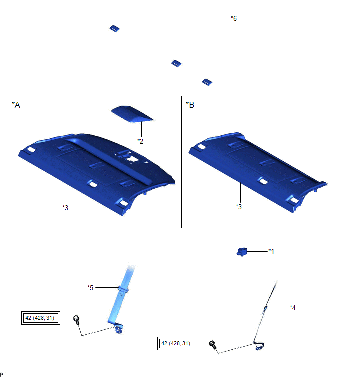
| *A | w/o Rear Sunshade | *B | w/ Rear Sunshade |
| *1 | BLIND SPOT MONITOR BUZZER | *2 | CENTER STOP LIGHT SET |
| *3 | PACKAGE TRAY TRIM PANEL ASSEMBLY | *4 | REAR SEAT OUTER BELT ASSEMBLY LH |
| *5 | REAR SEAT OUTER BELT ASSEMBLY RH | *6 | REAR SEAT SHOULDER BELT COVER |
.png) | Tightening torque for "Major areas involving basic vehicle performance such as moving/turning/stopping": N*m (kgf*cm, ft.*lbf) | - | - |
READ NEXT:
 Installation
INSTALLATION PROCEDURE 1. INSTALL BLIND SPOT MONITOR BUZZER (a) Connect the connector. (b) Engage the clamp to install the blind spot monitor buzzer. 2. INSTALL PACKAGE TRAY TRIM PANEL ASSEMBLY (w/o R
Removal
REMOVAL CAUTION / NOTICE / HINT The necessary procedures (adjustment, calibration, initialization, or registration) that must be performed after parts are removed and installed, or replaced during bli
Television Camera (for Front)
ComponentsCOMPONENTS ILLUSTRATION *1 COOL AIR INTAKE DUCT SEAL *2 FRONT TELEVISION CAMERA ASSEMBLY InstallationINSTALLATION PROCEDURE 1. INSTALL FRONT TELEVISION CAMERA ASSEMBLY (a) Eng
SEE MORE:
Components
COMPONENTS ILLUSTRATION *1 COOL AIR INTAKE DUCT SEAL *2 MILLIMETER WAVE RADAR SENSOR ASSEMBLY N*m (kgf*cm, ft.*lbf): Specified torque - -
Precaution
PRECAUTION PRECAUTION FOR DISCONNECTING CABLE FROM NEGATIVE AUXILIARY BATTERY TERMINAL NOTICE: When disconnecting the cable from the negative (-) auxiliary battery terminal, initialize the following system after the cable is reconnected. System Name See Procedure Lane Control System (for HV
© 2016-2026 Copyright www.lexguide.net
