Lexus ES: Removal
REMOVAL
CAUTION / NOTICE / HINT
The necessary procedures (adjustment, calibration, initialization, or registration) that must be performed after parts are removed and installed, or replaced during blind spot monitor buzzer removal/installation are shown below.
Necessary Procedure After Parts Removed/Installed/Replaced (for HV Model)| Replaced Part or Performed Procedure | Necessary Procedures | Effect/Inoperative Function When Necessary Procedures are not Performed | Link |
|---|---|---|---|
|
*: When performing learning using the Techstream.
Click here | |||
| Disconnect cable from negative auxiliary battery terminal | Perform steering sensor zero point calibration | Lane Control System | |
| Pre-collision System | |||
| Parking Support Brake System* | |||
| Lighting System | |||
| Memorize steering angle neutral point | Parking Assist Monitor System | | |
| Panoramic View Monitor System | | ||
| Initialize power trunk lid system | Power Trunk Lid System | | |
CAUTION:
Some of these service operations affect the SRS airbag system. Read the precautionary notices concerning the SRS airbag system before servicing.
.png)
Click here .gif)
NOTICE:
- After the power switch is turned off, the radio receiver assembly records various types of memory and settings. As a result, after turning the power switch off, make sure to wait at least 85 seconds before disconnecting the cable from the negative (-) auxiliary battery terminal. (for Audio and Visual System)
- After the power switch is turned off, the radio receiver assembly records various types of memory and settings. As a result, after turning the power switch off, make sure to wait at least 85 seconds before disconnecting the cable from the negative (-) auxiliary battery terminal. (for Navigation System)
| Replaced Part or Performed Procedure | Necessary Procedures | Effect/Inoperative Function When Necessary Procedures are not Performed | Link |
|---|---|---|---|
|
*: When performing learning using the Techstream.
Click here | |||
| Disconnect cable from negative battery terminal | Perform steering sensor zero point calibration | Lane Control System | |
| Pre-collision System | |||
| Parking Support Brake System* | |||
| Lighting System | |||
| Memorize steering angle neutral point | Parking Assist Monitor System | | |
| Panoramic View Monitor System | | ||
| Initialize power trunk lid system | Power Trunk Lid System | | |
CAUTION:
Some of these service operations affect the SRS airbag system. Read the precautionary notices concerning the SRS airbag system before servicing.
Click here
NOTICE:
- After the engine switch is turned off, the radio receiver assembly records various types of memory and settings. As a result, after turning the engine switch off, make sure to wait at least 85 seconds before disconnecting the cable from the negative (-) battery terminal. (for Audio and Visual System)
- After the engine switch is turned off, the radio receiver assembly records various types of memory and settings. As a result, after turning the engine switch off, make sure to wait at least 85 seconds before disconnecting the cable from the negative (-) battery terminal. (for Navigation System)
PROCEDURE
1. REMOVE REAR SEAT ASSEMBLY
Click here
2. REMOVE REAR DOOR SCUFF PLATE LH (for HV Model)
Click here
3. REMOVE REAR DOOR SCUFF PLATE LH (for Gasoline Model)
Click here
4. REMOVE REAR DOOR SCUFF PLATE RH (for HV Model)
HINT:
Use the same procedure as for the LH side.
5. REMOVE REAR DOOR SCUFF PLATE RH (for Gasoline Model)
HINT:
Use the same procedure as for the LH side.
6. REMOVE REAR SEAT SIDE GARNISH LH
Click here
7. REMOVE REAR SEAT SIDE GARNISH RH
HINT:
Use the same procedure as for the LH side.
8. REMOVE ROOF SIDE INNER GARNISH ASSEMBLY LH
Click here
9. REMOVE ROOF SIDE INNER GARNISH ASSEMBLY RH
HINT:
Use the same procedure as for the LH side.
10. DISCONNECT REAR SEAT OUTER BELT ASSEMBLY LH
Click here
11. DISCONNECT REAR SEAT OUTER BELT ASSEMBLY RH
HINT:
Use the same procedure as for the LH side.
12. REMOVE CENTER STOP LIGHT SET (w/o Rear Sunshade)
Click here
13. REMOVE REAR SEAT SHOULDER BELT COVER
Click here
14. REMOVE PACKAGE TRAY TRIM PANEL ASSEMBLY (w/o Rear Sunshade)
Click here
15. REMOVE PACKAGE TRAY TRIM PANEL ASSEMBLY (w/ Rear Sunshade)
Click here
16. REMOVE BLIND SPOT MONITOR BUZZER
| (a) Disengage the clamp. |
|
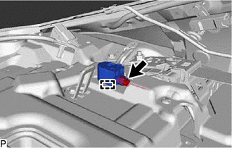
(b) Disconnect the connector to remove the blind spot monitor buzzer.
READ NEXT:
 Television Camera (for Front)
ComponentsCOMPONENTS ILLUSTRATION *1 COOL AIR INTAKE DUCT SEAL *2 FRONT TELEVISION CAMERA ASSEMBLY InstallationINSTALLATION PROCEDURE 1. INSTALL FRONT TELEVISION CAMERA ASSEMBLY (a) Eng
Components
COMPONENTS ILLUSTRATION *1 OUTER MIRROR *2 OUTER MIRROR COVER ASSEMBLY *3 SIDE TELEVISION CAMERA ASSEMBLY *4 OUTER MIRROR TAPE *5 CAMERA CONNECTOR CLAMP - - ● Non
SEE MORE:
Terminals Of Ecu
TERMINALS OF ECU CHECK LUGGAGE CLOSER MOTOR ASSEMBLY (a) Disconnect the R7 luggage closer motor assembly connector. (b) Measure the voltage and resistance according to the value(s) in the table below. Terminal No. (Symbol) Wiring Color Terminal Description Condition Specified Condition
How To Proceed With Troubleshooting
CAUTION / NOTICE / HINT HINT:
Use the following procedure to troubleshoot the power mirror control system (w/ Memory).
*: Use the Techstream.
PROCEDURE 1. VEHICLE BROUGHT TO WORKSHOP
NEXT 2. CUSTOMER PROBLEM ANALYSIS HINT:
In troubleshooting, confirm tha
