Lexus ES: Installation
INSTALLATION
PROCEDURE
1. INSPECT AND ADJUST BRAKE PEDAL HEIGHT
Click here .gif)
2. INSTALL BRAKE PEDAL STROKE SENSOR ASSEMBLY
NOTICE:
- Do not drop the brake pedal stroke sensor assembly.
- If the brake pedal stroke sensor assembly has been dropped, replace the brake pedal stroke sensor assembly with a new one.
(a) When installing a new brake pedal stroke sensor assembly:
NOTICE:
Do not break the brake pedal stroke sensor assembly lever set pin before installing the brake pedal stroke sensor assembly with the 2 nuts.
| (1) Install a new brake pedal stroke sensor assembly to the brake pedal support assembly with the 2 nuts. Torque: 8.5 N·m {87 kgf·cm, 75 in·lbf} NOTICE:
|
|
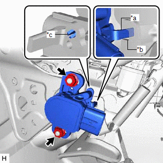
(2) Connect the connector.
(3) Firmly depress the brake pedal to break the brake pedal stroke sensor assembly lever set pin.
(4) Remove the broken lever set pin.
(b) When reusing the brake pedal stroke sensor assembly:
| (1) Install the brake pedal stroke sensor assembly to the brake pedal support assembly and temporarily tighten the 2 nuts. NOTICE:
|
|
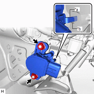
(2) Connect the connector.
3. INSTALL HYBRID VEHICLE CONTROL ECU
Click here
4. ADJUST BRAKE PEDAL STROKE SENSOR ASSEMBLY
NOTICE:
When the brake pedal stroke sensor assembly is being reused, perform the following procedure to adjust it.
(a) Connect the Techstream to the DLC3 with the power switch off.
(b) Turn the power switch on (IG).
(c) Turn the Techstream on.
(d) Enter the following menus: Chassis / ABS/VSC/TRAC / Data List / Stroke Sensor.
Chassis > ABS/VSC/TRAC > Data List| Tester Display |
|---|
| Stroke Sensor |
| (e) Read the stroke sensor value in the Data List, and turn the brake pedal stroke sensor assembly slowly to the right or left to adjust the output voltage so that it is within the following range. Standard Voltage (without the brake pedal depressed): 0.8 to 1.2 V |
|
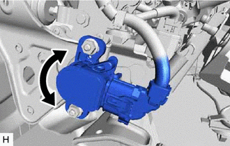
(f) Tighten the 2 nuts.
Torque:
8.5 N·m {87 kgf·cm, 75 in·lbf}
NOTICE:
Do not depress the brake pedal after turning the power switch on (IG).
(g) Turn the Techstream off and turn the power switch off.
(h) Disconnect the Techstream from the DLC3.
5. INSTALL NO. 1 INSTRUMENT PANEL UNDER COVER SUB-ASSEMBLY
Click here
6. PERFORM INITIALIZATION AND CALIBRATION
Perform linear solenoid valve offset learning, ABS holding solenoid valve learning, brake pedal stroke sensor assembly zero point calibration and system information memorization:
Click here
7. CHECK AND CLEAR DTC
Click here
READ NEXT:
 Removal
REMOVAL CAUTION / NOTICE / HINT The necessary procedures (adjustment, calibration, initialization, or registration) that must be performed after parts are removed, installed, or replaced during brake
ABS Operates Before Necessary When Braking
DESCRIPTION Troubleshooting for when ABS operates too soon due to a noisy signal from the speed sensor, a difference in output, etc. CAUTION / NOTICE / HINT NOTICE:
After replacing or removing and
SEE MORE:
System Description
SYSTEM DESCRIPTION ACTIVE NOISE CONTROL SYSTEM (a) The active noise control system is a system that detects muffled engine sounds produced in sync that fluctuates according to the engine speed, by using the active noise control microphone and outputs anti-phase control sound through the audio speake
Removal
REMOVAL PROCEDURE 1. REMOVE REAR NO. 1 FLOOR BOARD (for 2GR-FKS) (a) Remove the 4 clips (A). (b) Disengage the 3 grommets (B) and 2 clips (C) to remove the rear No. 1 floor board. 2. REMOVE REAR FLOOR SIDE MEMBER COVER (for A25A-FXS) (a) Remove the bolt and 8 clips (A).
