Lexus ES: Automatic Light Control Sensor
Components
COMPONENTS
ILLUSTRATION
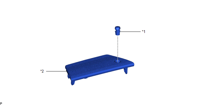
| *1 | AUTOMATIC LIGHT CONTROL SENSOR | *2 | NO. 1 SPEAKER OPENING COVER ASSEMBLY |
On-vehicle Inspection
ON-VEHICLE INSPECTION
PROCEDURE
1. INSPECT AUTOMATIC LIGHT CONTROL SENSOR
| (a) Disconnect the H3 automatic light control sensor connector. |
|
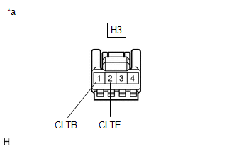
(b) Measure the voltage and resistance according to the value(s) in the table below.
Standard Voltage:
| Tester Connection | Condition | Specified Condition |
|---|---|---|
|
*1: for HV Model
*2: for Gasoline Model | ||
| H3-1 (CLTB) - H3-2 (CLTE) | Power switch off*1 | Below 1 V |
| Engine switch off*2 | ||
| Power switch on (IG)*1 | 11 to 14 V | |
| Engine switch on (IG)*2 | ||
Standard Resistance:
| Tester Connection | Condition | Specified Condition |
|---|---|---|
| H3-2 (CLTE) - Body ground | Always | Below 1 Ω |
If the result is not as specified, there may be a malfunction on the wire harness side.
(c) Connect the H3 automatic light control sensor connector.
(d) Connect an oscilloscope to terminals H3-2 (CLTE) and H3-4 (CLTS) of the automatic light control sensor connector and check the waveform.
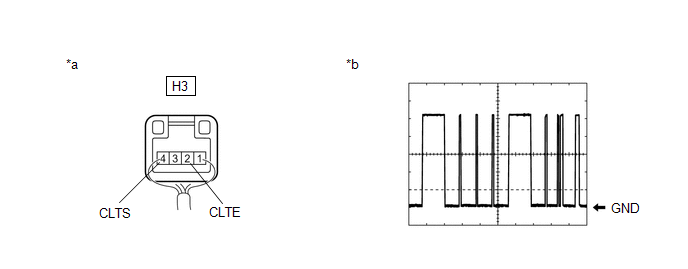
| *a | Component with harness connected (Automatic Light Control Sensor) | *b | Waveform |
OK:
| Tester Connection | Condition | Tool Setting | Specified Condition |
|---|---|---|---|
|
*1: for HV Model
*2: for Gasoline Model | |||
| H3-2 (CLTE) - H3-4 (CLTS) | Power switch on (IG)*1 | 2 V/DIV., 10 ms./DIV. | Pulse generation (See waveform) |
| Engine switch on (IG)*2 | |||
HINT:
The communication waveform changes according to the surrounding brightness.
If the result is not as specified, the automatic light control sensor may be malfunctioning.
Removal
REMOVAL
PROCEDURE
1. REMOVE NO. 1 SPEAKER OPENING COVER ASSEMBLY
Click here .gif)
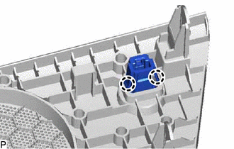
2. REMOVE AUTOMATIC LIGHT CONTROL SENSOR
| (a) Disengage the 2 claws to remove the automatic light control sensor. |
|
READ NEXT:
 Components
COMPONENTS ILLUSTRATION *A w/o Headup Display *B w/ Headup Display *1 COWL SIDE TRIM BOARD LH *2 FRONT DOOR OPENING TRIM COVER LH *3 FRONT DOOR SCUFF PLATE LH *4 HAZARD W
Removal
REMOVAL PROCEDURE 1. REMOVE AIR CONDITIONING CONTROL ASSEMBLY Click here 2. REMOVE FRONT DOOR SCUFF PLATE LH Click here 3. REMOVE COWL SIDE TRIM BOARD LH Click here 4. REMOVE FRONT DOOR OPENING
SEE MORE:
Data List / Active Test
DATA LIST / ACTIVE TEST DATA LIST HINT: Using the Techstream to read the Data List allows the values or states of switches, sensors, actuators and other items to be read without removing any parts. This non-intrusive inspection can be very useful because intermittent conditions or signals may be dis
Installation
INSTALLATION CAUTION / NOTICE / HINT NOTICE: This procedure includes the installation of small-head bolts. Refer to Small-Head Bolts of Basic Repair Hint to identify the small-head bolts. Click here PROCEDURE 1. INSTALL ENGINE OIL LEVEL SENSOR (a) Using an 8 mm socket wrench, install the engine oi
