Lexus ES: Components
Lexus ES (XZ10) Service Manual / Vehicle Interior / Lighting (ext) / Hazard Warning Switch / Components
COMPONENTS
ILLUSTRATION
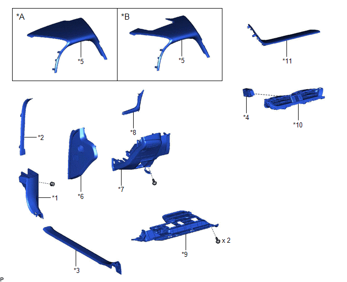
| *A | w/o Headup Display | *B | w/ Headup Display |
| *1 | COWL SIDE TRIM BOARD LH | *2 | FRONT DOOR OPENING TRIM COVER LH |
| *3 | FRONT DOOR SCUFF PLATE LH | *4 | HAZARD WARNING SIGNAL SWITCH ASSEMBLY |
| *5 | INSTRUMENT CLUSTER FINISH PANEL SUB-ASSEMBLY | *6 | INSTRUMENT SIDE PANEL LH |
| *7 | LOWER INSTRUMENT PANEL FINISH PANEL SUB-ASSEMBLY | *8 | NO. 1 INSTRUMENT CLUSTER MOULDING |
| *9 | NO. 1 INSTRUMENT PANEL UNDER COVER SUB-ASSEMBLY | *10 | NO. 2 INSTRUMENT PANEL REGISTER ASSEMBLY |
| *11 | UPPER INSTRUMENT PANEL FINISH PANEL SUB-ASSEMBLY | - | - |
READ NEXT:
 Removal
REMOVAL PROCEDURE 1. REMOVE AIR CONDITIONING CONTROL ASSEMBLY Click here 2. REMOVE FRONT DOOR SCUFF PLATE LH Click here 3. REMOVE COWL SIDE TRIM BOARD LH Click here 4. REMOVE FRONT DOOR OPENING
Inspection
INSPECTION PROCEDURE 1. INSPECT HAZARD WARNING SIGNAL SWITCH ASSEMBLY *a Component without harness connected (Hazard Warning Signal Switch Assembly) (a) Measure the resistance according to th
Installation
INSTALLATION PROCEDURE 1. INSTALL HAZARD WARNING SIGNAL SWITCH ASSEMBLY (a) Engage the 2 claws to install the hazard warning signal switch assembly. Install in this Direction 2. INSTALL NO.
SEE MORE:
Left Front Wheel Speed Sensor Circuit Short to Battery (C050012)
DESCRIPTION Each speed sensor detects wheel speed and sends signals to the skid control ECU (brake actuator assembly). These signals are used by the ABS control. The speed sensor detects the magnetic fields of the speed sensor rotor as it rotates and outputs a pulse signal. The frequency of the puls
Dtc Check / Clear
DTC CHECK / CLEAR CHECK FOR DTC (CHECK USING TECHSTREAM) (a) Connect the Techstream to the DLC3. (b) Turn the engine switch on (IG). (c) Turn the Techstream on. (d) Enter the following menus: Body Electrical / Active Noise Control / Trouble Codes. Body Electrical > Active Noise Control > Troub
© 2016-2026 Copyright www.lexguide.net
