Lexus ES: Inspection
INSPECTION
PROCEDURE
1. INSPECT FRONT DOOR ILLUMINATION LIGHT LH (FRONT DOOR OUTSIDE HANDLE ASSEMBLY LH)
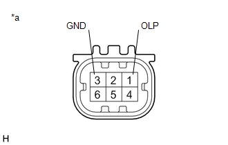
| *a | Component without harness connected (Front Door Illumination Light LH (Front Door Outside Handle Assembly LH)) |
(a) Connect 4 dry-cell batteries (1.5 V) in series.
NOTICE:
Do not use rechargeable batteries as they may not output a voltage of 1.5 V.
(b) Apply 6.0 V battery voltage to the front door illumination light LH (front door outside handle assembly LH) and check that the light illuminates.
OK:
| Measurement Condition | Specified Condition |
|---|---|
| Positive (+) lead from the batteries → Terminal 1 (OLP) Negative (-) lead from the batteries → Terminal 3 (GND) | Illumination light illuminates |
If the result is not as specified, replace the front door illumination light LH (front door outside handle assembly LH).
2. INSPECT FRONT DOOR ILLUMINATION LIGHT RH (FRONT DOOR OUTSIDE HANDLE ASSEMBLY RH)
| *a | Component without harness connected (Front Door Illumination Light RH (Front Door Outside Handle Assembly RH)) |
(a) Connect 4 dry-cell batteries (1.5 V) in series.
NOTICE:
Do not use rechargeable batteries as they may not output a voltage of 1.5 V.
(b) Apply 6.0 V battery voltage to the front door illumination light RH (front door outside handle assembly RH) and check that the light illuminates.
OK:
| Measurement Condition | Specified Condition |
|---|---|
| Positive (+) lead from the batteries → Terminal 1 (OLP) Negative (-) lead from the batteries → Terminal 3 (GND) | Illumination light illuminates |
If the result is not as specified, replace the front door illumination light RH (front door outside handle assembly RH).
READ NEXT:
 Installation
INSTALLATION CAUTION / NOTICE / HINT HINT:
Use the same procedure for the RH side and LH side.
The following procedure is for the LH side.
PROCEDURE 1. INSTALL FRONT DOOR ILLUMINATION LIGHT (F
Components
COMPONENTS ILLUSTRATION *1 COURTESY LIGHT ASSEMBLY *2 REAR DOOR ILLUMINATION LIGHT (REAR DOOR OUTSIDE HANDLE ASSEMBLY) *3 REAR DOOR SERVICE HOLE COVER *4 REAR DOOR TRIM BOARD SUB-A
SEE MORE:
Power Mirror Surface Position is not Memorized
DESCRIPTION If any of the M1, M2 or M3 seat memory switch is pressed, the outer mirror control ECU assembly (driver door) detects the switch operation and sends the seat memory switch signal to the main body ECU (multiplex network body ECU) via CAN communication. On receiving the seat memory switch
Back Camera Power Supply Failure (C1621)
DESCRIPTION This DTC is stored if the rear television camera assembly judges as a result of its self check that the signals or signal lines between the rear television camera assembly and parking assist ECU are not normal. DTC No. Detection Item DTC Detection Condition Trouble Area C162
