Lexus ES: Replacement
REPLACEMENT
CAUTION / NOTICE / HINT
NOTICE:
- Perform fluid replacement with the shift lever in P and the parking brake applied.
- Perform fluid replacement while maintaining the brake fluid level between the MAX and MIN lines on the brake fluid reservoir.
- If the No. 1 brake actuator hose (the hose between the brake booster pump assembly and brake master cylinder reservoir assembly) is higher than the fluid level when the pump motor is operating, air will enter the hose and brake booster pump assembly and it may become difficult to replace brake fluid.
- When performing fluid replacement, the accumulator pressure drop may cause a buzzer to sound. As this is not a malfunction, continue with the fluid replacement.
- If fluid replacement is performed, a motor drive permission malfunction or accumulator low pressure DTC may be stored. Clear the DTCs after performing fluid replacement or whenever specified by a procedure.
- Do not allow brake fluid to contact any painted surface. If brake fluid leaks onto any painted surface, immediately wash it off.
- When performing fluid replacement, do not continuously operate the pump motor for more than 100 seconds. If the pump motor is operated for more than 100 seconds, release the brake pedal to stop operation of the pump in order to prevent damage to the pump motor.
- As brake fluid may overflow from the reservoir when brake fluid is released from the accumulator, do not invert and place the brake fluid bottle on the reservoir filler opening.
HINT:
There are 2 ways of brake fluid replacement: using the Techstream or not using the Techstream.
PROCEDURE
1. REPLACE BRAKE FLUID (when Using the Techstream)
(a) Fill the reservoir with brake fluid.
|
(1) Remove the brake master cylinder reservoir filler cap assembly. |
|
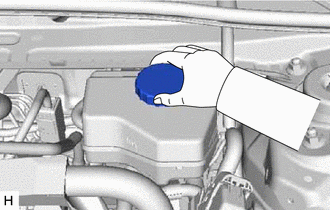
(2) Add brake fluid to the reservoir until the fluid level is between the MAX and MIN lines on the brake fluid reservoir.
Brake Fluid:
SAE J1703 or FMVSS No. 116 DOT3
SAE J1704 or FMVSS No. 116 DOT4
(b) Replace the brake fluid.
(1) Connect the Techstream to the DLC3 and turn the power switch on (IG).
(2) Turn the Techstream on and enter the following menus: Chassis / ABS/VSC/TRAC / Utility / Air Bleeding/AHB-R Utility.
Chassis > ABS/VSC/TRAC > Utility|
Tester Display |
|---|
|
Air Bleeding/AHB-R Utility |
(3) Select "Brake Line Air Bleeding", and replace the brake fluid following the instructions on the Techstream.
HINT:
When the brake pedal is released, the piston inside the master cylinder may take longer than the brake pedal to return to its original position. Therefore, make sure to wait for 1 second or more between each depression of the brake pedal.
(4) After replacing brake fluid, tighten each bleeder plug.
Torque:
8.3 N·m {85 kgf·cm, 73 in·lbf}
(c) Install the brake master cylinder reservoir filler cap assembly.
(d) Clear the DTCs.
Click here .gif)
(e) Turn the Techstream off then turn the power switch off.
(f) Inspect for brake fluid leaks.
2. REPLACE BRAKE FLUID (when Not Using the Techstream)
NOTICE:
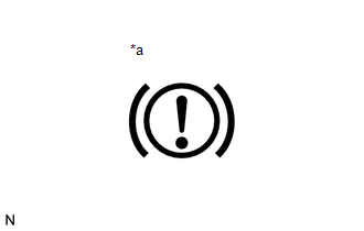
- Performing the following procedure enters ECB (Electronically Controlled Brake system) Invalid Mode without using the Techstream.
- ECB (Electronically Controlled Brake system) Invalid Mode allows the brake fluid to be replaced without using the Techstream.
- The brake warning light blinks (yellow) to indicate that ECB (Electronically Controlled Brake system) Invalid Mode is selected.
- Be sure to confirm that the brake warning light is blinking (yellow) throughout the brake fluid replacement procedure.
- If any of the following conditions are met, ECB (Electronically Controlled
Brake system) Invalid Mode is canceled and the brake warning light (yellow)
turns off. Do not allow ECB (Electronically Controlled Brake system) Invalid
Mode to be canceled while replacing brake fluid or DTCs may be stored.
The shift lever is moved from P to any other position.
The power switch is turned on (READY).
The power switch is turned off.
The parking brake is released.
The vehicle speed is more than 0 km/h (0 mph).
- Do not rotate any brake disc while ECB (Electronically Controlled Brake system) Invalid Mode is selected.
- Although the brake warning light will blink (yellow) and a buzzer will sound while performing fluid replacement, this is not a malfunction.
(a) Remove all 4 wheels.
Click here
(b) Enter ECB (Electronically Controlled Brake system) Invalid Mode.
(1) Perform the procedure listed below within 1 minute.
- Turn the power switch on (IG) with the shift lever in P and parking brake applied.
- Move the shift lever to N and then depress the brake pedal more than 8 times within 5 seconds.
- Move the shift lever to P and then depress the brake pedal more than 8 times within 5 seconds.
- Move the shift lever to N and then depress the brake pedal more than 8 times within 5 seconds.
- Move the shift lever to P.
|
(2) Check that the brake warning light is blinking (yellow). |
|
(c) Fill the reservoir with brake fluid.
|
(1) Remove the brake master cylinder reservoir filler cap assembly. |
|
(2) Add brake fluid to the reservoir until the fluid level is between the MAX and MIN lines on the brake fluid reservoir.
Brake Fluid:
SAE J1703 or FMVSS No. 116 DOT3
SAE J1704 or FMVSS No. 116 DOT4
(d) Replace the brake fluid.
HINT:
When replacing the brake fluid using vacuum, the brake fluid bottle can be inverted and placed on the reservoir filler opening.
(1) Connect a vinyl tube to the bleeder plug of the front disc brake cylinder assembly RH.
(2) Depress the brake pedal several times with approximately 1 second between each depression, and then loosen the bleeder plug with the pedal depressed.*1
(3) When brake fluid stops coming out, tighten the bleeder plug and then release the brake pedal for 1 second or more.*2
HINT:
When the brake pedal is released, the piston inside the master cylinder may take longer than the brake pedal to return to its original position. Therefore, make sure to wait for 1 second or more between each depression of the brake pedal.
(4) Repeat steps *1 and *2 until new brake fluid comes out.
(5) Tighten the bleeder plug completely.
Torque:
8.3 N·m {85 kgf·cm, 73 in·lbf}
(6) Replace brake fluid from the front disc brake cylinder assembly LH using the same procedure as for the RH side.
(7) Connect a vinyl tube to the bleeder plug of the rear disc brake cylinder assembly LH.
(8) Depress the brake pedal several times with approximately 1 second between each depression, and then loosen the bleeder plug with the pedal depressed.*3
(9) When brake fluid stops coming out, tighten the bleeder plug and then release the brake pedal for 1 second or more.*4
HINT:
When the brake pedal is released, the piston inside the master cylinder may take longer than the brake pedal to return to its original position. Therefore, make sure to wait for 1 second or more between each depression of the brake pedal.
(10) Repeat steps *3 and *4 until new brake fluid comes out.
(11) Tighten the bleeder plug completely.
Torque:
8.3 N·m {85 kgf·cm, 73 in·lbf}
(12) Replace brake fluid from the rear disc brake cylinder assembly RH using the same procedure as for the LH side.
(13) Turn the power switch off.
(e) Inspect for brake fluid leaks.
(f) Adjust the brake fluid level in the reservoir.
Click here
(g) Install the brake master cylinder reservoir filler cap assembly.
(h) Install the 4 wheels.
Click here
READ NEXT:
 Components
COMPONENTS
ILLUSTRATION
*1
FRONT CENTER UPPER SUSPENSION BRACE SUB-ASSEMBLY
-
-
Tightening torque for "Major areas involv
Removal
REMOVAL
PROCEDURE
1. REMOVE COWL TOP VENTILATOR LOUVER SUB-ASSEMBLY
Click here
2. REMOVE FRONT CENTER UPPER SUSPENSION BRACE SUB-ASSEMBLY
Click here
3. REMOVE UNION TO CHECK VALVE HOSE
SEE MORE:
Precaution
PRECAUTION PRECAUTION FOR DISCONNECTING CABLE FROM NEGATIVE AUXILIARY BATTERY TERMINAL NOTICE: When disconnecting the cable from the negative (-) auxiliary battery terminal, initialize the following systems after the cable is reconnected. System Name See Procedure Lane Control System (for H
Hybrid/EV Battery Stack 1 Delta SOC High (P1A8000,P1AD01B)
DESCRIPTION The battery voltage sensor and the hybrid vehicle control ECU calculate the SOC (state of charge) of the HV battery through the accumulated amperage in the HV battery. The battery voltage sensor sends the condition of the HV battery to the hybrid vehicle control ECU. Then the hybrid vehi
