Lexus ES: Adjustment
ADJUSTMENT
CAUTION / NOTICE / HINT
NOTICE:
Before adjusting the park/neutral position switch assembly, check that the shift lever is in N.
PROCEDURE
1. SECURE VEHICLE
(a) Fully apply the parking brake and chock a wheel.
CAUTION:
- Make sure to apply the parking brake and chock a wheel before performing this procedure.
- If the vehicle is not secure and the shift lever is moved to N, the vehicle may suddenly move, possibly resulting in an accident or serious injury.
.png)
2. DISCONNECT TRANSMISSION CONTROL CABLE ASSEMBLY
Click here .gif)
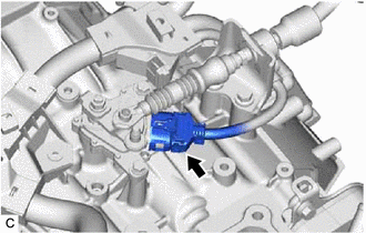
3. ADJUST PARK/NEUTRAL POSITION SWITCH ASSEMBLY
| (a) Disconnect the park/neutral position switch assembly connector. |
|
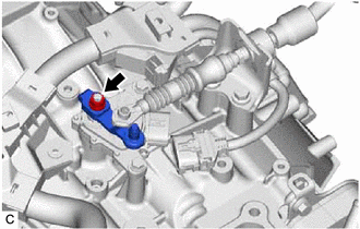
| (b) Remove the nut, washer and transmission control shaft lever from the manual valve lever shaft sub-assembly. |
|
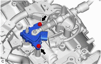
| (c) Loosen the 2 bolts of the park/neutral position switch assembly. |
|
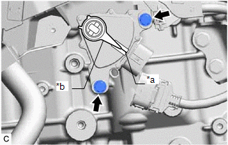
| (d) Align the protrusion with the neutral basic line. |
|
(e) Hold the park/neutral position switch assembly in position and tighten the 2 bolts.
Torque:
5.4 N·m {55 kgf·cm, 48 in·lbf}
(f) Install the transmission control shaft lever to the manual valve lever shaft sub-assembly with the washer and nut.
Torque:
12.7 N·m {130 kgf·cm, 9 ft·lbf}
(g) Connect the park/neutral position switch assembly connector.
4. CONNECT TRANSMISSION CONTROL CABLE ASSEMBLY
Click here
5. INSPECT PARK/NEUTRAL POSITION SWITCH ASSEMBLY OPERATION
Click here
READ NEXT:
 Components
COMPONENTS ILLUSTRATION *1 BATTERY CLAMP SUB-ASSEMBLY - - N*m (kgf*cm, ft.*lbf): Specified torque - - ILLUSTRATION *1 TRANSMISSION CONTROL CABLE ASSEMBLY *2 TRANSMISS
Inspection
INSPECTION PROCEDURE 1. INSPECT PARK/NEUTRAL POSITION SWITCH ASSEMBLY (a) Measure the resistance according to the value(s) in the table below when the transmission control shaft lever is moved to e
Installation
INSTALLATION PROCEDURE 1. INSTALL PARK/NEUTRAL POSITION SWITCH ASSEMBLY (a) Temporarily install the park/neutral position switch assembly to the automatic transaxle case sub-assembly with the 2 bolts.
SEE MORE:
Maintenance requirements
To ensure safe and economical driving,
day-to-day care and regular
maintenance are essential. It is the
owner's responsibility to perform
regular checks. Lexus recommends
the following maintenance:
■Repair and replacement
It is recommended that genuine Lexus parts
be used for repairs to en
USB Audio System Recognition/Play Error
DESCRIPTION When a USB device or "iPod" is connected to the USB jack of the No. 1 stereo jack adapter assembly, it must have playable files. The device must also communicate with and be recognized by the radio receiver assembly. This diagnostic procedure is for when a device is not recognized, or fi
