Lexus ES: Adjustment
ADJUSTMENT
PROCEDURE
1. SECURE VEHICLE
(a) Fully apply the parking brake and chock a wheel.
CAUTION:
- Make sure to apply the parking brake and chock a wheel before performing this procedure.
- If the vehicle is not secure and the shift lever is moved to N, the vehicle may suddenly move, possibly resulting in an accident or serious injury.
.png)
2. REMOVE CONSOLE BOX ASSEMBLY
Click here .gif)
3. ADJUST SHIFT LEVER POSITION
NOTICE:
Before adjusting the transmission control cable assembly, check that the shift lever position sensor and shift lever are in N.
HINT:
Whether the transmission control cable assembly is type A or type B can be determined by the shape of the end.
.png)
| *A | Type A | *B | Type B |
(a) for Type A:
| (1) Disconnect the transmission control cable assembly from the transmission floor shift assembly. |
|
.png)
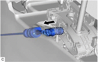
| (2) Slide the slider of the transmission control cable assembly in the direction indicated by the arrow in the illustration and pull the lock piece outward. |
|
.png)
| (3) Connect the transmission control cable assembly to the transmission floor shift assembly. NOTICE:
|
|
.png)
| (4) Push the lock piece into the adjuster case. NOTICE:
|
|
.png)
(5) After adjusting the shift lever position, check the position and operation of the shift lever. If there is a problem, adjust the shift lever position again.
(b) for Type B:
| (1) Disconnect the transmission control cable assembly from the transmission floor shift assembly. |
|
| (2) Rotate the lock nut counterclockwise approximately 180° and, while holding the lock nut in that position, disconnect the transmission control cable assembly from the transmission floor shift assembly. |
|
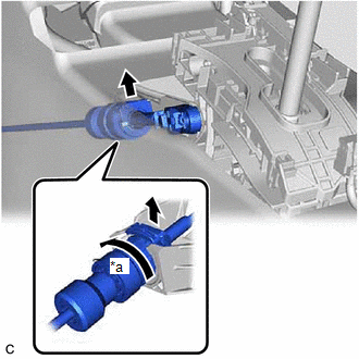
| (3) Slide the adjuster case cover in the direction shown by the arrow. |
|
.png)
| (4) Using a precision screwdriver, pull out the lock piece of the adjuster case. |
|
.png)
| (5) Turn the lock nut of the transmission control cable assembly counterclockwise. While holding the lock nut, push in the stopper. |
|
.png)
| (6) Connect the transmission control cable assembly to the transmission floor shift assembly. NOTICE: After installation, check that the outer part of the stopper is as shown in the illustration. |
|
.png)
| (7) Connect the transmission control cable assembly to the transmission floor shift assembly. NOTICE:
|
|
.png)
| (8) Push in the lock piece of the adjuster case to lock it. |
|
.png)
| (9) Move the adjuster case cover in the direction shown by the arrow. NOTICE: If the adjuster case cover is not moved far enough so that the adjuster case cover engages the lock piece, the transmission control cable assembly will not be able to lock, and reliable shift operation will not be possible. |
|
.png)
4. INSTALL CONSOLE BOX ASSEMBLY
Click here
READ NEXT:
 Components
COMPONENTS ILLUSTRATION *1 COOL AIR INTAKE DUCT SEAL *2 INLET AIR CLEANER ASSEMBLY *3 NO. 1 ENGINE COVER SUB-ASSEMBLY *4 AIR CLEANER ASSEMBLY WITH AIR CLEANER HOSE *5 FRONT L
Installation
INSTALLATION PROCEDURE 1. INSTALL TRANSMISSION CONTROL CABLE ASSEMBLY (a) Turn the control shaft lever clockwise until it stops, then turn it counterclockwise 2 notches. (b) Engage the
Removal
REMOVAL CAUTION / NOTICE / HINT The necessary procedures (adjustment, calibration, initialization or registration) that must be performed after parts are removed and installed, or replaced during tran
SEE MORE:
Customize Parameters
CUSTOMIZE PARAMETERS CUSTOMIZE LUGGAGE COMPARTMENT DOOR OPENER SYSTEM NOTICE:
When the customer requests a change in a function, first make sure that the function can be customized.
Be sure to make a note of the current settings before customizing.
When troubleshooting a function, first make
Removal
REMOVAL CAUTION / NOTICE / HINT The necessary procedures (adjustment, calibration, initialization, or registration) that must be performed after parts are removed and installed, or replaced during rear trailing arm assembly removal/installation are shown below. Necessary Procedures After Parts Remov
