Lexus ES: Removal
REMOVAL
CAUTION / NOTICE / HINT
The necessary procedures (adjustment, calibration, initialization or registration) that must be performed after parts are removed and installed, or replaced during transmission control cable assembly removal/installation are shown below.
Necessary Procedures After Parts Removed/Installed/Replaced| Replaced Part or Performed Procedure | Necessary Procedure | Effect/Inoperative Function when Necessary Procedure not Performed | Link |
|---|---|---|---|
| Inspection After Repair |
| |
CAUTION:
To prevent burns, do not touch the engine, exhaust pipe or other high temperature components while the engine is hot.
.png)
PROCEDURE
1. SECURE VEHICLE
(a) Fully apply the parking brake and chock a wheel.
CAUTION:
- Make sure to apply the parking brake and chock a wheel before performing this procedure.
- If the vehicle is not secure and the shift lever is moved to N, the vehicle may suddenly move, possibly resulting in an accident or serious injury.
.png)
2. REMOVE COOL AIR INTAKE DUCT SEAL
Click here .gif)
.gif)
3. REMOVE INLET AIR CLEANER ASSEMBLY
Click here .gif)
.gif)
.gif)
4. REMOVE NO. 1 ENGINE COVER SUB-ASSEMBLY
Click here .gif)
.gif)
.gif)
5. REMOVE AIR CLEANER ASSEMBLY WITH AIR CLEANER HOSE
Click here .gif)
.gif)
.gif)
6. REMOVE FRONT EXHAUST PIPE ASSEMBLY (TWC: Rear Catalyst)
Click here .gif)
7. REMOVE FRONT LOWER NO. 1 FLOOR HEAT INSULATOR
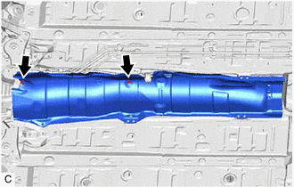
| (a) Remove the 2 nuts and front lower No. 1 floor heat insulator from the vehicle body. |
|
8. REMOVE TRANSMISSION FLOOR SHIFT ASSEMBLY
Click here .gif)
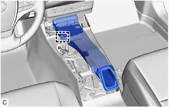
9. REMOVE NO. 1 CONSOLE BOX DUCT
| (a) Disengage the clamp to separate the wire harness. |
|
(b) Remove the No. 1 console box duct.
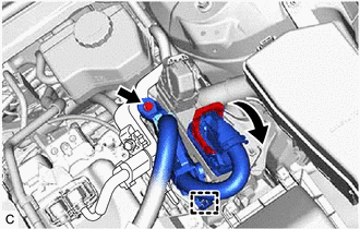
10. DISCONNECT ENGINE ROOM MAIN WIRE
| (a) Rotate the lever while pushing the lock, and disconnect the ECM connector. NOTICE: After disconnecting the ECM connector, make sure that dirt, water or other foreign matter does not contact the connecting parts of the ECM connector. |
|
(b) Remove the bolt and separate the engine room main wire from the No. 2 ECM bracket.
(c) Disengage the clamp.
11. REMOVE TRANSMISSION CONTROL CABLE ASSEMBLY
(a) Move the shift lever to N.
| (b) Remove the nut and disconnect the transmission control cable assembly from the control shaft lever. |
|
| (c) Using a screwdriver, disengage the 4 claws and disconnect the transmission control cable assembly with the clip from the No. 1 transmission control cable bracket. |
|
| (d) Using a screwdriver, disengage the 2 claws and remove the clip from the transmission control cable assembly. |
|
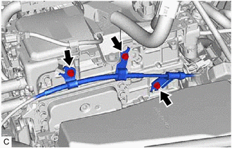
| (e) Remove the 3 bolts and disconnect the transmission control cable assembly from the inverter with converter assembly. |
|
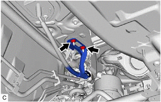
| (f) Remove the 2 nuts and disconnect the transmission control cable assembly from the vehicle body. |
|
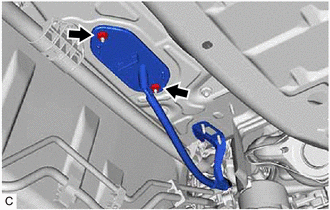
| (g) Remove the 2 nuts and then remove the transmission control cable assembly from the vehicle body. |
|

.png)
.png)
.png)
