
Lexus ES: Parts Location
PARTS LOCATION
ILLUSTRATION
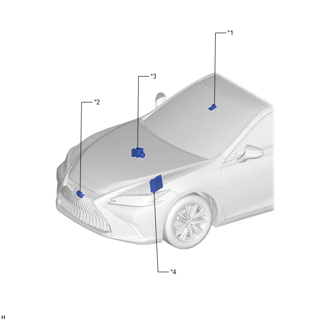
| *1 | FORWARD RECOGNITION CAMERA | *2 | MILLIMETER WAVE RADAR SENSOR ASSEMBLY |
| *3 | BRAKE ACTUATOR ASSEMBLY - SKID CONTROL ECU | *4 | ECM |
ILLUSTRATION
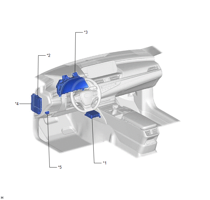
| *1 | AIRBAG ECU ASSEMBLY - YAW RATE SENSOR | *2 | MAIN BODY ECU (MULTIPLEX NETWORK BODY ECU) |
| *3 | COMBINATION METER ASSEMBLY | *4 | INSTRUMENT PANEL JUNCTION BLOCK ASSEMBLY - ECU-IG1 NO. 3 FUSE |
| *5 | DLC3 | - | - |
READ NEXT:
 Precaution
PRECAUTION PRECAUTION FOR DISCONNECTING CABLE FROM NEGATIVE BATTERY TERMINAL NOTICE: When disconnecting the cable from the negative (-) battery terminal, initialize the following systems after the cab
System Diagram
SYSTEM DIAGRAM
Customize Parameters
CUSTOMIZE PARAMETERS CUSTOMIZE ROAD SIGN ASSIST SYSTEM NOTICE: Be sure to make a note of the current settings before customizing. (a) Customizing with the multi-information display (1) Turn the engine
SEE MORE:
Removal
REMOVAL CAUTION / NOTICE / HINT The necessary procedures (adjustment, calibration, initialization, or registration) that must be performed after parts are removed and installed, or replaced during black out tape removal/installation are shown below. Necessary Procedure After Parts Removed/Installed/
Generator Phase U Current Sensor Signal Bias Level Out of Range / Zero Adjustment Failure (P0E0028,...,P0E0828)
DTC SUMMARY MALFUNCTION DESCRIPTION These DTCs indicate that the current sensor value is abnormal. The cause of this malfunction may be one of the following: Internal inverter malfunction
Current sensor malfunction
Inverter with converter assembly internal circuit malfunction
DESCRIPTION The
© 2016-2026 Copyright www.lexguide.net
