Lexus ES: A25a-fks Spark Plug
Removal
REMOVAL
CAUTION / NOTICE / HINT
The necessary procedures (adjustment, calibration, initialization or registration) that must be performed after parts are removed and installed, or replaced during spark plug removal/installation are shown below.
Necessary Procedures After Parts Removed/Installed/Replaced|
Replaced Part or Performed Procedure |
Necessary Procedure |
Effect/Inoperative Function when Necessary Procedure not Performed |
Link |
|---|---|---|---|
|
Inspection after repair |
|
|
NOTICE:
This procedure includes the removal of small-head bolts. Refer to Small-Head Bolts of Basic Repair Hint to identify the small-head bolts.
Click here .gif)
PROCEDURE
1. REMOVE NO. 1 ENGINE COVER SUB-ASSEMBLY
Click here
2. REMOVE IGNITION COIL ASSEMBLY
Click here
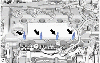
3. REMOVE SPARK PLUG
|
(a) Remove the 4 spark plugs from the cylinder head sub-assembly. NOTICE: If a spark plug has been struck or dropped, replace it. HINT: Arrange the removed parts in the correct order. |
|
Installation
INSTALLATION
CAUTION / NOTICE / HINT
NOTICE:
This procedure includes the installation of small-head bolts. Refer to Small-Head Bolts of Basic Repair Hint to identify the small-head bolts.
Click here .gif)
PROCEDURE
1. INSTALL SPARK PLUG
HINT:
Perform "Inspection After Repair" after replacing a spark plug.
Click here
(a) Install the 4 spark plugs to the cylinder head sub-assembly.
Torque:
20 N·m {204 kgf·cm, 15 ft·lbf}
NOTICE:
If a spark plug has been struck or dropped, replace it.
HINT:
Install the same parts to their original positions.
2. INSTALL IGNITION COIL ASSEMBLY
Click here
3. INSTALL NO. 1 ENGINE COVER SUB-ASSEMBLY
Click here
4. PERFORM INITIALIZATION
(a) Perform "Inspection After Repair" after replacing an ignition coil assembly or spark plug.
Click here
READ NEXT:
 A25a-fxs Air Cleaner Filter Element
Components
COMPONENTS
ILLUSTRATION
*1
AIR CLEANER CAP SUB-ASSEMBLY
*2
AIR CLEANER FILTER ELEMENT SUB-ASSEMBLY
Removal
REMOVAL
PROCEDURE
Components
COMPONENTS
ILLUSTRATION
*1
AUXILIARY BATTERY
*2
BATTERY HOSE
*3
NEGATIVE AUXILIARY BATTERY TERMINAL
*4
SEE MORE:
Smart access system with push-button
start
The following operations can be
performed simply by carrying the
electronic key on your person, for
example in your pocket. The driver
should always carry the electronic
key.
Locks and unlocks the doors
Opens the trunk
Starts the hybrid system
■Antenna location
Antennas outsi
Brake Switch "A" Circuit Short to Battery (P057112)
DESCRIPTION The skid control ECU (brake actuator assembly) receives stop light switch assembly signals and uses them to determine whether or not the brakes are applied. DTCs may be stored if either of the following occurs:
Stop light switch assembly stuck on malfunction.
The accelerator and bra
