Lexus ES: 2gr-fks Spark Plug
Components
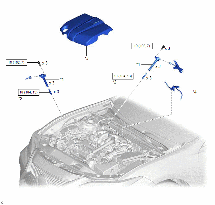
COMPONENTS
ILLUSTRATION
|
*1 |
IGNITION COIL ASSEMBLY |
*2 |
SPARK PLUG |
|
*3 |
V-BANK COVER SUB-ASSEMBLY |
*4 |
VACUUM HOSE |
.png) |
N*m (kgf*cm, ft.*lbf): Specified torque |
- |
- |
Removal
REMOVAL
CAUTION / NOTICE / HINT
The necessary procedures (adjustment, calibration, initialization, or registration) that must be performed after parts are removed and installed, or replaced during spark plug removal/installation are shown below.
Necessary Procedures After Parts Removed/Installed/Replaced|
Replaced Part or Performed Procedure |
Necessary Procedure |
Effect/Inoperative Function when Necessary Procedure not Performed |
Link |
|---|---|---|---|
|
Inspection after repair |
|
|
PROCEDURE
1. REMOVE V-BANK COVER SUB-ASSEMBLY
Click here .gif)
2. REMOVE IGNITION COIL ASSEMBLY
Click here
3. REMOVE SPARK PLUG
|
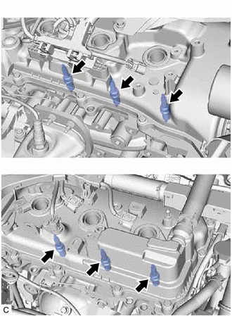
(a) Remove the 6 spark plugs from the cylinder head sub-assembly and cylinder head LH. NOTICE: If a spark plug has been struck or dropped, replace it. HINT: Arrange the removed parts in the correct order. |
|
Installation
INSTALLATION
PROCEDURE
1. INSTALL SPARK PLUG
HINT:
Perform "Inspection After Repair" after replacing a spark plug.
Click here .gif)
(a) Install the 6 spark plugs to the cylinder head sub-assembly and cylinder head LH.
Torque:
18 N·m {184 kgf·cm, 13 ft·lbf}
NOTICE:
If a spark plug has been struck or dropped, replace it.
HINT:
Install the same parts to their original positions.
2. INSTALL IGNITION COIL ASSEMBLY
Click here
3. INSTALL V-BANK COVER SUB-ASSEMBLY
Click here
4. PERFORM INITIALIZATION
(a) Perform "Inspection After Repair" after replacing an ignition coil assembly or spark plug.
Click here
READ NEXT:
 A25a-fks Air Cleaner Filter Element
Components
COMPONENTS
ILLUSTRATION
*1
AIR CLEANER CAP SUB-ASSEMBLY
*2
AIR CLEANER FILTER ELEMENT SUB-ASSEMBLY
Removal
REMOVAL
PROCEDURE
A25a-fks Battery
Components
COMPONENTS
ILLUSTRATION
*1
BATTERY
*2
NEGATIVE BATTERY TERMINAL
*3
POSITIVE BATTERY TERMINAL
*4
SEE MORE:
Inspection
INSPECTION PROCEDURE 1. INSPECT REAR SPEAKER ASSEMBLY (for 10 Speakers) (a) With the speaker installed, check that there is no looseness or other abnormalities. (b) Check that there is no foreign matter in the speaker, no tears on the speaker cone or other abnormalities. (c) Measure the resistanc
Fuel Rail Pressure Sensor "A" Circuit Short to Battery or Open (P019015)
DESCRIPTION Refer to DTC P019011. Click here DTC No. Detection Item DTC Detection Condition Trouble Area MIL Memory Note P019015 Fuel Rail Pressure Sensor "A" Circuit Short to Battery or Open The fuel pressure sensor (for high pressure side) output voltage is higher than 4.9
