Lexus ES: A25a-fks Air Cleaner Filter Element
Components
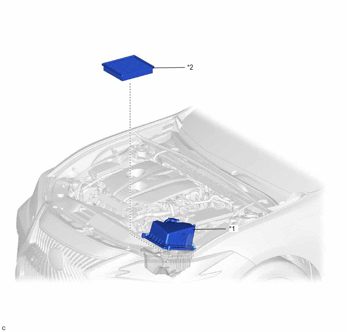
COMPONENTS
ILLUSTRATION
|
*1 |
AIR CLEANER CAP SUB-ASSEMBLY |
*2 |
AIR CLEANER FILTER ELEMENT SUB-ASSEMBLY |
Removal
REMOVAL
PROCEDURE
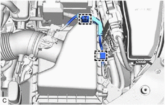
1. SEPARATE AIR CLEANER CAP SUB-ASSEMBLY
|
(a) Disengage the 2 wire harness clamps. |
|
|
(b) Disengage the 2 air cleaner cap clamps. |
|
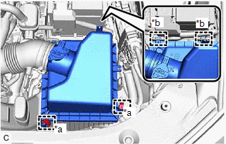
(c) Disengage the 2 guides to separate the air cleaner cap sub-assembly from the air cleaner case sub-assembly.
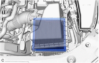
2. REMOVE AIR CLEANER FILTER ELEMENT SUB-ASSEMBLY
|
(a) Remove the air cleaner filter element sub-assembly from the air cleaner case sub-assembly. NOTICE: Do not allow foreign matter to enter the air cleaner cap sub-assembly and air cleaner case sub-assembly. |
|
3. INSPECT AIR CLEANER FILTER ELEMENT SUB-ASSEMBLY
HINT:
This procedure is only performed when the air cleaner filter element sub-assembly will be reused.
(a) Check whether the air cleaner filter element sub-assembly is dirty or clogged.
|
(b) If the air cleaner filter element sub-assembly is dirty or has foreign matter adhered to it, clean the air cleaner filter element sub-assembly with compressed air. NOTICE: When cleaning the air cleaner filter element sub-assembly, blow the compressed air from the intake downstream side (from the air cleaner cap sub-assembly side). HINT: If the air cleaner filter element sub-assembly is still extremely dirty after cleaning it, replace the air cleaner filter element sub-assembly with a new one. |
|
.png)
Installation
INSTALLATION
PROCEDURE
1. INSTALL AIR CLEANER FILTER ELEMENT SUB-ASSEMBLY
(a) Check that the inside of the air cleaner case sub-assembly does not have dirt or deposits, and clean them away if they are present.
(b) Install the air cleaner filter element sub-assembly to the air cleaner case sub-assembly.
2. INSTALL AIR CLEANER CAP SUB-ASSEMBLY
(a) Engage the 2 guides to install the air cleaner cap sub-assembly to the air cleaner case sub-assembly.
(b) Engage the 2 air cleaner cap clamps.
(c) Engage the 2 wire harness clamps.
READ NEXT:
 A25a-fks Battery
Components
COMPONENTS
ILLUSTRATION
*1
BATTERY
*2
NEGATIVE BATTERY TERMINAL
*3
POSITIVE BATTERY TERMINAL
*4
Components
COMPONENTS
ILLUSTRATION
*1
RADIATOR CAP SUB-ASSEMBLY
*2
RADIATOR DRAIN COCK PLUG
*3
NO. 1 ENGINE UNDER COVER
-
SEE MORE:
Essential information
Emergency flashers
The emergency flashers are used to
warn other drivers when the vehicle
has to be stopped in the road due to
a breakdown, etc.
Operating instructions
Press the switch to flash all of the turn
signal lights.
To turn them off, press the switch once
again.
■Emergency f
Components
COMPONENTS ILLUSTRATION *1 LUGGAGE COMPARTMENT FLOOR MAT *2 SPARE WHEEL COVER TRAY ILLUSTRATION *1 REAR FLOOR FINISH PLATE *2 LUGGAGE HOLD BELT STRIKER ASSEMBLY ILLUSTRATION *A for LH Side *B for RH Side *C w/o Power Trunk Lid System *D w/ Power Trunk Li
