Lexus ES: Horn
Components
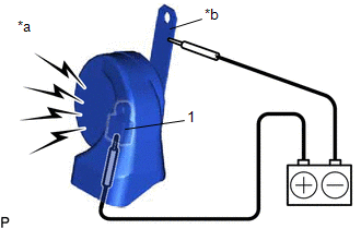
COMPONENTS
ILLUSTRATION
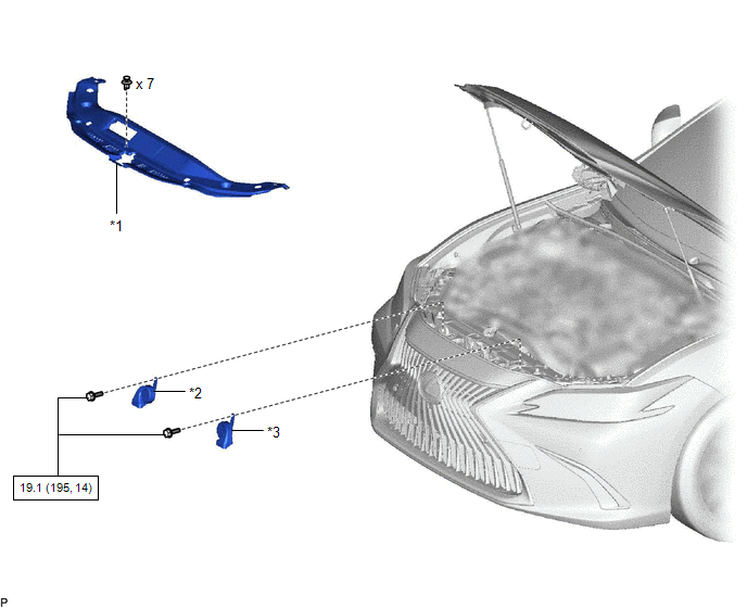
| *1 | COOL AIR INTAKE DUCT SEAL | *2 | HIGH PITCHED HORN ASSEMBLY |
| *3 | LOW PITCHED HORN ASSEMBLY | - | - |
.png) | N*m (kgf*cm, ft.*lbf): Specified torque | - | - |
Removal
REMOVAL
PROCEDURE
1. REMOVE COOL AIR INTAKE DUCT SEAL
Click here .gif)
2. REMOVE HIGH PITCHED HORN ASSEMBLY
| (a) Remove the bolt. |
|
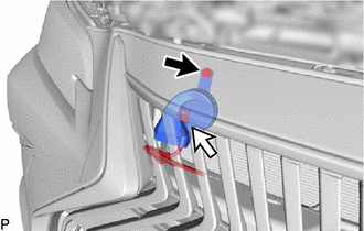
(b) Disconnect the connector to remove the high pitched horn assembly.
3. REMOVE LOW PITCHED HORN ASSEMBLY
| (a) Remove the bolt. |
|
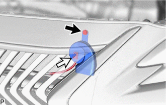
(b) Disconnect the connector to remove the low pitched horn assembly.
Inspection
INSPECTION
PROCEDURE
1. INSPECT HIGH PITCHED HORN ASSEMBLY
| (a) Apply auxiliary battery voltage and check the operation of the high pitched horn assembly according to the table below. OK:
If the result is not as specified, replace the high pitched horn assembly. |
|
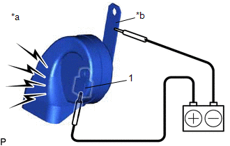
2. INSPECT LOW PITCHED HORN ASSEMBLY
| (a) Apply auxiliary battery voltage and check the operation of the low pitched horn assembly according to the table below. OK:
If the result is not as specified, replace the low pitched horn assembly. |
|
Installation
INSTALLATION
PROCEDURE
1. INSTALL LOW PITCHED HORN ASSEMBLY
(a) Connect the connector.
(b) Install the low pitched horn assembly with the bolt.
Torque:
19.1 N·m {195 kgf·cm, 14 ft·lbf}
2. INSTALL HIGH PITCHED HORN ASSEMBLY
(a) Connect the connector.
(b) Install the high pitched horn assembly with the bolt.
Torque:
19.1 N·m {195 kgf·cm, 14 ft·lbf}
3. INSTALL COOL AIR INTAKE DUCT SEAL
Click here .gif)
READ NEXT:
 Parts Location
PARTS LOCATION ILLUSTRATION *A for Type A *B for Type B *1 HIGH PITCHED HORN ASSEMBLY *2 LOW PITCHED HORN ASSEMBLY *3 HORN RELAY *4 ENGINE ROOM RELAY BLOCK AND JUNCTION B
Precaution
PRECAUTION PRECAUTION FOR DISCONNECTING CABLE FROM NEGATIVE AUXILIARY BATTERY TERMINAL NOTICE: When disconnecting the cable from the negative (-) auxiliary battery terminal, initialize the following s
SEE MORE:
Steering Angle Sensor Output (C1434)
DESCRIPTION Steering angle sensor signals are input to the skid control ECU (brake booster with master cylinder assembly) via the CAN communication system. HINT: When a malfunction occurs in the communication line to the steering angle sensor, U0126 (Lost Communication With Steering Angle Sensor Mod
How To Proceed With Troubleshooting
CAUTION / NOTICE / HINT HINT:
Use the following procedure to troubleshoot the sliding roof system.
*: Use the Techstream.
PROCEDURE 1. VEHICLE BROUGHT TO WORKSHOP
NEXT 2. CUSTOMER PROBLEM ANALYSIS HINT:
In troubleshooting, confirm that the problem sympto
