Lexus ES: Reassembly
REASSEMBLY
PROCEDURE
1. INSTALL VACUUM WARNING SWITCH ASSEMBLY
(a) Install a new check valve grommet to the brake booster assembly.
(b) Install the vacuum warning switch assembly to the brake booster assembly as shown in the illustration.
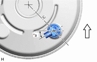
| *a | 30° +/- 20° |
 | Up |
2. INSTALL BRAKE VACUUM CHECK VALVE ASSEMBLY
(a) Install a new check valve grommet to the brake booster assembly.
(b) Install the brake vacuum check valve assembly to the brake booster assembly.
READ NEXT:
 Removal
REMOVAL CAUTION / NOTICE / HINT The necessary procedures (adjustment, calibration, initialization or registration) that must be performed after parts are removed and installed, or replaced during brak
Components
COMPONENTS ILLUSTRATION *1 FRONT CENTER UPPER SUSPENSION BRACE SUB-ASSEMBLY - - Tightening torque for "Major areas involving basic vehicle performance such as moving/turning/stopping"
SEE MORE:
Precaution
PRECAUTION PRECAUTION FOR DISCONNECTING CABLE FROM NEGATIVE AUXILIARY BATTERY TERMINAL NOTICE: When disconnecting the cable from the negative (-) auxiliary battery terminal, initialize the following system(s) after the cable is reconnected. System Procedure Lane Control System (for HV Model
Generator Resolver Circuit
DESCRIPTION The cause of this malfunction may be the generator resolver. Check the generator resolver internal resistance and connection condition from the inverter to the resolver. Related Parts Check Area Inspection Wire harness and connector between the inverter and generator resolver
© 2016-2026 Copyright www.lexguide.net
