Lexus ES: Inspection
INSPECTION
PROCEDURE
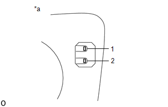
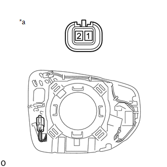
1. INSPECT OUTER MIRROR RH
| (a) Check the outer mirror heater operation. (1) Measure the resistance according to the value(s) in the table below. Standard Resistance:
If the result is not as specified, replace the outer mirror RH. |
|
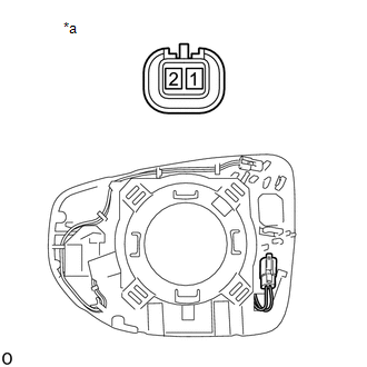
| (b) Check EC mirror operation. (1) Connect a new 1.5 V dry-cell battery. (2) Apply 1.5 V dry-cell battery voltage to the terminals of the connector, and check that the EC mirror operation. NOTICE: Do not apply a voltage of more than 1.5 V. OK:
If the result is not as specified, replace the outer mirror RH. |
|
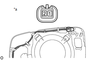
(c) Check the operation of the outer rear view mirror indicator. (w/ Blind Spot Monitor System)
NOTICE:
Do not apply a voltage of more than 6 V.
(1) Connect 4 new 1.5 V dry-cell batteries in series.
| (2) Apply 6 V battery voltage to the terminals of the connector, and check that the outer rear view mirror indicator comes on. OK:
If the result is not as specified, replace the outer mirror RH. |
|
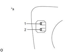
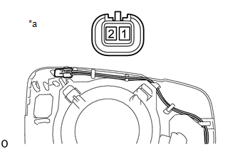
2. INSPECT OUTER MIRROR LH
| (a) Check the outer mirror heater operation. (1) Measure the resistance according to the value(s) in the table below. Standard Resistance:
If the result is not as specified, replace the outer mirror LH. |
|
| (b) Check EC mirror operation. (1) Connect a new 1.5 V dry-cell battery. (2) Apply 1.5 V dry-cell battery voltage to the terminals of the connector, and check that the EC mirror operation. NOTICE: Do not apply a voltage of more than 1.5 V. OK:
If the result is not as specified, replace the outer mirror LH. |
|
(c) Check the operation of the outer rear view mirror indicator. (w/ Blind Spot Monitor System)
NOTICE:
Do not apply a voltage of more than 6 V.
(1) Connect 4 new 1.5 V dry-cell batteries in series.
| (2) Apply 6 V battery voltage to the terminals of the connector, and check that the outer rear view mirror indicator comes on. OK:
If the result is not as specified, replace the outer mirror LH. |
|
READ NEXT:
 Installation
INSTALLATION CAUTION / NOTICE / HINT HINT:
Use the same procedure for the RH side and LH side.
The following procedure is for the LH side.
PROCEDURE 1. INSTALL OUTER MIRROR (a) w/o Blind Spot
Precaution
PRECAUTION PRECAUTION FOR DISCONNECTING CABLE FROM NEGATIVE BATTERY TERMINAL NOTICE: When disconnecting the cable from the negative (-) battery terminal, initialize the following systems after the cab
SEE MORE:
Check For Intermittent Problems
CHECK FOR INTERMITTENT PROBLEMS CHECK FOR INTERMITTENT PROBLEMS (a) Perform a simulation test. (1) For the simulation test, reproduce the driving conditions that were present when the problem occurred. These conditions should be based on the customer's comments and freeze frame data that is recorded
GVIF Disconnected (from Park Assist/Monitoring ECU to EMV/MM Integrated Device) (B1574)
DESCRIPTION The multi-display assembly and parking assist ECU are connected via video signal (digital) lines. This DTC is stored when a video signal (digital) line is disconnected. DTC No. Detection Item DTC Detection Condition Trouble Area B1574 GVIF Disconnected (from Park Assist/Mo
