Lexus ES: Touch Pad Sensor Malfunction (B1559)
DESCRIPTION
This DTC is stored if the remote touch (remote operation controller assembly) detects a malfunction in itself, such as internal hardware failure or remote touch screen sensor malfunction.
| DTC No. | Detection Item | DTC Detection Condition | Trouble Area |
|---|---|---|---|
| B1559 | Touch Pad Sensor Malfunction | Internal remote touch screen sensor malfunction | Remote touch (remote operation controller assembly) |
PROCEDURE
| 1. | CHECK DTC |
(a) Clear the DTCs.
Body Electrical > Navigation System > Clear DTCs(b) Recheck for DTCs and check that no DTCs are output.
Body Electrical > Navigation System > Trouble CodesOK:
No DTCs are output.
HINT:
-
If DTC B155B is output, perform troubleshooting for DTC B155B first.
Click here
.gif)
- Remote touch screen touch detection is performed using the electrostatic sensor and G sensor. However, there is no effect on the basic functions of the remote touch screen when the G sensor is not operating. Therefore, a counter is used to prevent DTCs from being output immediately (in order to reduce excessive DTC output). Therefore, when DTCs are not output, it is necessary to turn the engine switch from on (ACC) to off and check for DTCs again.
| OK | .gif) | USE SIMULATION METHOD TO CHECK |
|
.gif)
| 2. | REMOTE TOUCH (REMOTE OPERATION CONTROLLER ASSEMBLY) SELF CHECK (CHECK REMOTE TOUCH SCREEN OPERATION POSITION RECOGNITION CONDITION) |
(a) Enter self-diagnostic mode.
Click here
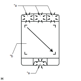
| (b) Operate the remote touch screen diagonally from the upper left to the lower right and check that the brightness of the switch illumination changes. NOTICE: Since the remote touch screen may recognize a pinch in/out operation if operated with 2 fingers, always use 1 finger to operate the remote touch screen in self-diagnostic mode. OK: Brightness changes according to remote touch screen operation.
|
|
| B | | REPLACE REMOTE TOUCH (REMOTE OPERATION CONTROLLER ASSEMBLY) |
|
| 3. | CHECK DTC |
(a) Clear the DTCs.
Body Electrical > Navigation System > Clear DTCs(b) Turn the engine switch off.
(c) Turn the engine switch on (ACC) and wait for 40 seconds.
(d) Recheck for DTCs and check that no DTCs are output.
Body Electrical > Navigation System > Trouble CodesOK:
No DTCs are output.
HINT:
Remote touch screen touch detection is performed using the electrostatic sensor and G sensor. However, there is no effect on the basic functions of the remote touch screen when the G sensor is not operating. Therefore, a counter is used to prevent DTCs from being output immediately (in order to reduce excessive DTC output). Therefore, when DTCs are not output, it is necessary to turn the engine switch from on (ACC) to off and check for DTCs again.
| OK | | USE SIMULATION METHOD TO CHECK |
| NG | | REPLACE REMOTE TOUCH (REMOTE OPERATION CONTROLLER ASSEMBLY) |
READ NEXT:
 GVIF Disconnected (from Park Assist/Monitoring ECU to EMV/MM Integrated Device) (B1574)
DESCRIPTION DTC No. Detection Item DTC Detection Condition Trouble Area B1574 GVIF Disconnected (from Park Assist/Monitoring ECU to EMV/MM Integrated Device) GVIF disconnected (from p
GVIF Disconnected (from EMV/MM Integrated Device to Multi Display) (B1575)
DESCRIPTION The radio receiver assembly and multi-display assembly are connected via video signal (digital) lines. This DTC is stored when a video signal (digital) line is disconnected. DTC No. D
Voice Recognition Microphone Disconnected (B1579)
DESCRIPTION The radio receiver assembly and telephone microphone assembly are connected to each other using the microphone connection detection signal lines. This DTC is stored when a microphone conne
SEE MORE:
Smart access system with push-button
start
The following operations can be
performed simply by carrying the
electronic key on your person, for
example in your pocket. The driver
should always carry the electronic
key.
Locks and unlocks the doors
Opens the trunk
Starts the hybrid system
■Antenna location
Antennas outsi
Installation
INSTALLATION CAUTION / NOTICE / HINT HINT:
Use the same procedure for the RH side and LH side.
The following procedure is for the LH side.
PROCEDURE 1. INSTALL FRONT NO. 4 SPEAKER ASSEMBLY (for 17 Speakers) NOTICE: Do not touch the speaker cone. (a) Engage the 2 guides to temporarily install
