Lexus ES: Installation
INSTALLATION
CAUTION / NOTICE / HINT
HINT:
- Use the same procedure for the RH side and LH side.
- The following procedure is for the LH side.
PROCEDURE
1. INSTALL FRONT NO. 4 SPEAKER ASSEMBLY (for 17 Speakers)
NOTICE:
Do not touch the speaker cone.
(a) Engage the 2 guides to temporarily install the front No. 4 speaker assembly.
(b) Install the front No. 4 speaker assembly with the 2 screws.
2. INSTALL FRONT NO. 1 SPEAKER ASSEMBLY
NOTICE:
Do not touch the speaker cone.
(a) Connect the connector.
(b) Engage the 2 guides to temporarily install the front No. 1 speaker assembly.
(c) Install the front No. 1 speaker assembly with the 4 screws.
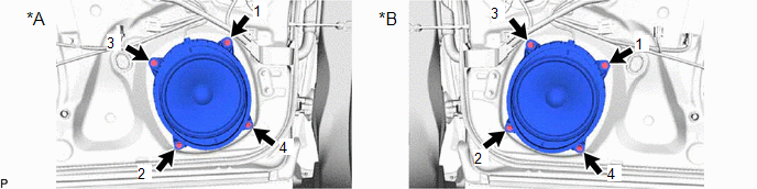
| *A | for LH Side | *B | for RH Side |
HINT:
Install the screws in the order shown in the illustration.
3. INSTALL FRONT DOOR TRIM BOARD SUB-ASSEMBLY
Click here .gif)
4. INSTALL COURTESY LIGHT ASSEMBLY
Click here
5. INSTALL MULTIPLEX NETWORK MASTER SWITCH ASSEMBLY WITH FRONT DOOR UPPER ARMREST BASE PANEL (for Driver Side)
Click here
6. INSTALL POWER WINDOW REGULATOR SWITCH ASSEMBLY WITH FRONT DOOR UPPER ARMREST BASE PANEL (for Front Passenger Side)
Click here
7. INSTALL NO. 2 DOOR TRIM PAD
Click here
8. INSPECT POWER WINDOW OPERATION
for HV Model: Click here
for Gasoline Model: Click here
READ NEXT:
 Removal
REMOVAL CAUTION / NOTICE / HINT HINT:
Use the same procedure for the RH side and LH side.
The following procedure is for the LH side.
PROCEDURE 1. REMOVE NO. 2 DOOR TRIM PAD Click here 2.
Components
COMPONENTS ILLUSTRATION *A for Side *B for Center *1 COWL SIDE TRIM BOARD *2 FRONT DOOR OPENING TRIM COVER *3 FRONT DOOR SCUFF PLATE *4 FRONT NO. 2 SPEAKER ASSEMBLY *
SEE MORE:
Installation
INSTALLATION CAUTION / NOTICE / HINT for HV Model:
When removing or installing the front disc brake caliper assembly, pushing back the disc brake piston may cause a large clearance between the brake pads and brake disc. When the brake pedal is depressed with a large clearance between the brake pa
Certification ECU Vehicle Information Reading/Writing Process Malfunction (B15F7)
DESCRIPTION This DTC is stored when items controlled by the certification ECU (smart key ECU assembly) cannot be customized via the audio and visual system vehicle customization screen. HINT: The certification ECU (smart key ECU assembly) controls the smart access system with push-button start (for
