Lexus ES: GVIF Disconnected (from Park Assist/Monitoring ECU to EMV/MM Integrated Device) (B1574)
DESCRIPTION
| DTC No. | Detection Item | DTC Detection Condition | Trouble Area |
|---|---|---|---|
| B1574 | GVIF Disconnected (from Park Assist/Monitoring ECU to EMV/MM Integrated Device) | GVIF disconnected (from parking assist ECU to multi-display assembly) |
|
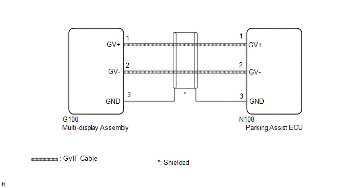
WIRING DIAGRAM
CAUTION / NOTICE / HINT
NOTICE:
Depending on the parts that are replaced during vehicle inspection or maintenance, performing initialization, registration or calibration may be needed. Refer to Precaution for Audio and Visual System.
Click here .gif)
PROCEDURE
| 1. | CHECK DTC |
(a) Clear the DTCs.
Body Electrical > Navigation System > Clear DTCs(b) Turn the engine switch off.
(c) Recheck for DTCs and check that no DTCs are output.
Body Electrical > Navigation System > Trouble CodesOK:
No DTCs are output.
| OK |  | USE SIMULATION METHOD TO CHECK |
|

| 2. | CHECK HARNESS AND CONNECTOR (MULTI-DISPLAY ASSEMBLY - PARKING ASSIST ECU) |
| (a) Disconnect the G100 multi-display assembly connector. |
|
(b) Disconnect the N108 parking assist ECU connector.
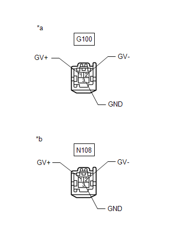
(c) Measure the resistance according to the value(s) in the table below.
Standard Resistance:
| Tester Connection | Condition | Specified Condition |
|---|---|---|
| N108-1 (GV+) - G100-1 (GV+) | Always | Below 1 Ω |
| N108-2 (GV-) - G100-2 (GV-) | Always | Below 1 Ω |
| N108-3 (GND) - G100-3 (GND) | Always | Below 1 Ω |
| N108-1 (GV+) or G100-1 (GV+) - Body ground | Always | 10 kΩ or higher |
| N108-2 (GV-) or G100-2 (GV-) - Body ground | Always | 10 kΩ or higher |
| N108-3 (GND) or G100-3 (GND) - Body ground | Always | 10 kΩ or higher |
| NG | | REPAIR OR REPLACE HARNESS OR CONNECTOR |
|
| 3. | CHECK MULTI-DISPLAY ASSEMBLY |
(a) Replace the multi-display assembly with a new or known good one.
Click here
(b) Clear the DTCs.
Body Electrical > Navigation System > Clear DTCs(c) Turn the engine switch off.
(d) Recheck for DTCs and check that no DTCs are output.
Body Electrical > Navigation System > Trouble CodesOK:
No DTCs are output.
| OK | | END (MULTI-DISPLAY ASSEMBLY IS DEFECTIVE) |
| NG | | REPLACE PARKING ASSIST ECU |
READ NEXT:
 GVIF Disconnected (from EMV/MM Integrated Device to Multi Display) (B1575)
DESCRIPTION The radio receiver assembly and multi-display assembly are connected via video signal (digital) lines. This DTC is stored when a video signal (digital) line is disconnected. DTC No. D
Voice Recognition Microphone Disconnected (B1579)
DESCRIPTION The radio receiver assembly and telephone microphone assembly are connected to each other using the microphone connection detection signal lines. This DTC is stored when a microphone conne
USB Device Malfunction (B1585)
DESCRIPTION This DTC is stored when a malfunction occurs in a connected device. DTC No. Detection Item DTC Detection Condition Trouble Area B1585 USB Device Malfunction When any of th
SEE MORE:
System Too Lean Bank 1 (P017100,P017200,P117000,P117B00)
DESCRIPTION The fuel trim is related to the feedback compensation value, not to the basic injection duration. The fuel trim consists of both the short-term and long-term fuel trims. The short-term fuel trim is fuel compensation that is used to constantly maintain the air fuel ratio at stoichiometric
4wd Control Ecu
ComponentsCOMPONENTS ILLUSTRATION *1 NO. 3 INSTRUMENT PANEL TO COWL BRACE SUB-ASSEMBLY *2 4WD ECU ASSEMBLY N*m (kgf*cm, ft.*lbf): Specified torque - - InstallationINSTALLATION PROCEDURE 1. INSTALL 4WD ECU ASSEMBLY (a) Install the 4WD ECU assembly to the instrument panel rei
