Lexus ES: Tire Pressure Monitor Receiver Communication Stop (B1247)
DESCRIPTION
The main body ECU (multiplex network body ECU) and tire pressure warning ECU and receiver communicate by direct line. If a malfunction occurs in this communication signal, B1247 is output by the main body ECU (multiplex network body ECU).
| DTC No. | Detection Item | DTC Detection Condition | Trouble Area | Note |
|---|---|---|---|---|
| B1247 | Tire Pressure Monitor Receiver Communication Stop | Communication between the tire pressure warning ECU and receiver and main body ECU (multiplex network body ECU) is interrupted for 10 seconds or more. |
| This DTC is for main body ECU (multiplex network body ECU) |
WIRING DIAGRAM

CAUTION / NOTICE / HINT
NOTICE:
- When replacing the tire pressure warning ECU and receiver, read the transmitter IDs and number of the transmitters (4 or 5) stored in the old ECU using the Techstream and write them down before removal.
-
It is necessary to perform initialization
 after registration of the transmitter IDs into the tire pressure warning ECU and receiver after the ECU has been replaced.
-
Before replacing the main body ECU (multiplex network body ECU), refer to Registration.
Click here
PROCEDURE
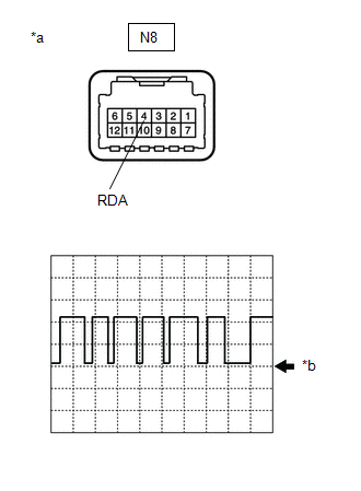
| 1. | INSPECT TIRE PRESSURE WARNING ECU AND RECEIVER (OUTPUT WAVEFORM) |
| (a) Using an oscilloscope, check the waveform. NOTICE: With the connector connected, check from the backside of the connector. OK:
|
|
| Result | Proceed to |
|---|---|
| Waveform is as shown in the illustration. (Waveform alternates between 10.5 V or higher and 0.5 V or less) | A |
| Waveform does not change from 10.5 V or higher | B |
| Waveform does not change from 0.5 V or less | C |
| A |  | REPLACE MAIN BODY ECU (MULTIPLEX NETWORK BODY ECU) |
| B | | REPLACE TIRE PRESSURE WARNING ECU AND RECEIVER |
|
.gif)
| 2. | CHECK TERMINAL VOLTAGE (MAIN BODY ECU (MULTIPLEX NETWORK BODY ECU) OUTPUT) |
(a) Disconnect the N8 tire pressure warning ECU and receiver connector.
(b) Measure the voltage according to the value(s) in the table below.
Standard Voltage:
| Tester Connection | Condition | Specified Condition |
|---|---|---|
| N8-4 (RDA) - Body ground | Power switch on (IG) | 10.5 V or higher |
| OK | | REPLACE TIRE PRESSURE WARNING ECU AND RECEIVER |
|
| 3. | CHECK HARNESS AND CONNECTOR (MAIN BODY ECU (MULTIPLEX NETWORK BODY ECU) - TIRE PRESSURE WARNING ECU AND RECEIVER) |
(a) Turn the power switch off.
(b) Disconnect the G38 main body ECU (multiplex network body ECU) connector.
(c) Measure the resistance according to the value(s) in the table below.
Standard Resistance:
| Tester Connection | Condition | Specified Condition |
|---|---|---|
| G38-10 (RDA) - N8-4 (RDA) | Always | Below 1 Ω |
| G38-10 (RDA) or N8-4 (RDA) - Body ground | Always | 10 kΩ or higher |
| OK | | REPLACE MAIN BODY ECU (MULTIPLEX NETWORK BODY ECU) |
| NG | | REPAIR OR REPLACE HARNESS OR CONNECTOR |
READ NEXT:
 Transmitter ID1 Operation Stop (C2111-C2114)
DESCRIPTION The tire pressure warning valve and transmitters that are installed in the tire and wheel assemblies measure the tire pressure of each wheel. The measured values are transmitted to the tir
Transmitter ID 1 not Received (Main) (C2121-C2124,C2181-C2184)
DESCRIPTION The tire pressure warning valve and transmitters that are installed in the tire and wheel assemblies measure the tire pressure of each wheel. The measured values are transmitted to the tir
Transmitter ID not Received (Main) (C2126)
DESCRIPTION If ID registration via the automatic ID registration function is canceled or the tire pressure warning ECU and receiver does not receive data from the tire pressure warning valve and trans
SEE MORE:
MOST Communication Malfunction (B15D0)
DESCRIPTION Navigation system components communicate with each other via MOST communication. If a line short or short to ground occurs in a MOST communication line, communication will not be possible and the navigation system will not operate normally. After the power switch is turned on (ACC), if t
Inspection
INSPECTION PROCEDURE 1. INSPECT OIL PUMP RELIEF VALVE (a) Coat the oil pump relief valve with engine oil, then check that it falls smoothly into the valve hole by its own weight. HINT: If the oil pump relief valve does not fall smoothly, replace the oil pump assembly. 2. INSPECT OIL P
