Lexus ES: Tire Pressure Monitor ECU Communication Stop (C2179)
DESCRIPTION
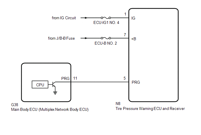
The main body ECU (multiplex network body ECU) sends signals to the tire pressure warning ECU and receiver via a direct line.
| DTC No. | Detection Item | DTC Detection Condition | Trouble Area | Note |
|---|---|---|---|---|
| C2179 | Tire Pressure Monitor ECU Communication Stop | Communication between the main body ECU (multiplex network body ECU) and tire pressure warning ECU and receiver is interrupted for 10 seconds or more. |
| - |
WIRING DIAGRAM
CAUTION / NOTICE / HINT
NOTICE:
- When replacing the tire pressure warning ECU and receiver, read the transmitter IDs and number of the transmitters (4 or 5) stored in the old ECU using the Techstream and write them down before removal.
-
It is necessary to perform initialization
.gif) after registration of the transmitter IDs into the tire pressure warning ECU and receiver after the ECU has been replaced.
after registration of the transmitter IDs into the tire pressure warning ECU and receiver after the ECU has been replaced.
-
Before replacing the main body ECU (multiplex network body ECU), refer to Registration.
Click here
PROCEDURE
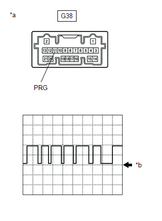
| 1. | INSPECT MAIN BODY ECU (MULTIPLEX NETWORK BODY ECU) (OUTPUT WAVEFORM) |
| (a) Using an oscilloscope, check the waveform. NOTICE: With the connector connected, check from the backside of the connector. OK:
|
|
| Result | Proceed to |
|---|---|
| Waveform is as shown in the illustration. (Waveform alternates between 9.8 V or higher and 1.2 V or less) | A |
| Waveform does not change from 9.8 V or higher | B |
| Waveform does not change from 1.2 V or less | C |
| A | .gif) | REPLACE TIRE PRESSURE WARNING ECU AND RECEIVER |
| B | | REPLACE MAIN BODY ECU (MULTIPLEX NETWORK BODY ECU) |
|
.gif)
| 2. | CHECK TERMINAL VOLTAGE (TIRE PRESSURE WARNING ECU AND RECEIVER OUTPUT) |
(a) Disconnect the G38 main body ECU (multiplex network body ECU) connector.
(b) Measure the voltage according to the value(s) in the table below.
Standard Voltage:
| Tester Connection | Condition | Specified Condition |
|---|---|---|
| G38-11 (PRG) - Body ground | Power switch on (IG) | 9.8 V or higher |
| OK | | REPLACE MAIN BODY ECU (MULTIPLEX NETWORK BODY ECU) |
|
| 3. | CHECK HARNESS AND CONNECTOR (TIRE PRESSURE WARNING ECU AND RECEIVER - MAIN BODY ECU (MULTIPLEX NETWORK BODY ECU)) |
(a) Turn the power switch off.
(b) Disconnect the N8 tire pressure warning ECU and receiver connector.
(c) Measure the resistance according to the value(s) in the table below.
Standard Resistance:
| Tester Connection | Condition | Specified Condition |
|---|---|---|
| N8-5 (PRG) - G38-11 (PRG) | Always | Below 1 Ω |
| N8-5 (PRG) or G38-11 (PRG) - Body ground | Always | 10 kΩ or higher |
| NG | | REPAIR OR REPLACE HARNESS OR CONNECTOR |
|
| 4. | CHECK HARNESS AND CONNECTOR (POWER SUPPLY - TIRE PRESSURE WARNING ECU AND RECEIVER) |
(a) Measure the voltage according to the value(s) in the table below.
Standard Voltage:
| Tester Connection | Condition | Specified Condition |
|---|---|---|
| N8-7 (+B) - Body ground | Always | 10 to 16 V |
| N8-1 (IG) - Body ground | Power switch on (IG) | 10 to 16 V |
| OK | | REPLACE TIRE PRESSURE WARNING ECU AND RECEIVER |
| NG | | REPAIR OR REPLACE HARNESS OR CONNECTOR |
READ NEXT:
 Initialization Switch Error (for Test Diagnosis) (C2198)
DESCRIPTION The switch circuit inside the combination meter assembly turns on and off according to the steering pad switch assembly operation. During test mode, the tire pressure warning light blinks
Lost Communication with Brake System Control Module (U0129)
DESCRIPTION The tire pressure warning ECU and receiver receives signals from the skid control ECU (brake booster with master cylinder assembly) via CAN communication system. DTC No. Detection Ite
Tire Position Not Identified
DESCRIPTION The tire pressure warning ECU and receiver identifies the tire position for each tire pressure warning valve and transmitter according to the wheel speed signals from the skid control ECU
SEE MORE:
Installation
INSTALLATION CAUTION / NOTICE / HINT HINT: for Side:
Use the same procedure for the RH side and LH side.
The following procedure is for the LH side.
PROCEDURE 1. INSTALL FRONT NO. 3 SPEAKER ASSEMBLY (for Center) NOTICE: Do not touch the speaker cone. (a) Connect the connector. (b) Install
Torque Sensor Zero Point Adjustment Undone (C1515)
DESCRIPTION This DTC does not indicate a malfunction. The power steering ECU (rack and pinion power steering gear assembly) stores this DTC when it determines that torque sensor zero point calibration has not been performed. When the IG terminal voltage is below 8 V, torque sensor zero point calibra
