Lexus ES: Relay
On-vehicle Inspection
ON-VEHICLE INSPECTION
PROCEDURE
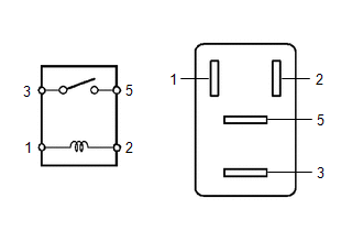
1. INSPECT MAIN RELAY (EFI-MAIN NO. 1)
| (a) Measure the resistance according to the value(s) in the table below. Standard Resistance:
If the result is not as specified, replace the main relay (EFI-MAIN NO. 1). |
|
2. INSPECT MAIN RELAY (EFI-MAIN NO. 2)
| (a) Measure the resistance according to the value(s) in the table below. Standard Resistance:
If the result is not as specified, replace the main relay (EFI-MAIN NO. 2). |
|
3. INSPECT MAIN RELAY (A/F HTR)
| (a) Measure the resistance according to the value(s) in the table below. Standard Resistance:
If the result is not as specified, replace the main relay (A/F HTR). |
|
4. INSPECT ELECTRONIC DRIVER UNIT RELAY (D INJ)
| (a) Measure the resistance according to the value(s) in the table below. Standard Resistance:
If the result is not as specified, replace the electronic driver unit relay (D INJ). |
|
5. INSPECT NO. 2 IGNITION RELAY (IG2 NO. 1)
| (a) Measure the resistance according to the value(s) in the table below. Standard Resistance:
If the result is not as specified, replace the No. 2 ignition relay (IG2 NO. 1). |
|
READ NEXT:
 Precaution
PRECAUTION INITIALIZATION NOTICE:
Before replacing the ECM, refer to Registration.
Click here
Perform Registration (VIN registration) after replacing the ECM.
Click here
Perform Learning
Definition Of Terms
DEFINITION OF TERMS Term Definition Monitor Description Description of what the ECM monitors and how it detects malfunctions (monitoring purpose and details). Related DTCs Group of di
SEE MORE:
Reassembly
REASSEMBLY PROCEDURE 1. INSTALL BRAKE MASTER CYLINDER RESERVOIR STRAINER 2. INSTALL BRAKE MASTER CYLINDER RESERVOIR FILLER CAP ASSEMBLY 3. INSTALL MASTER CYLINDER RESERVOIR GROMMET (a) Apply a light layer of lithium soap base glycol grease to the entire circumference of 2 new master cylinder reservo
Telescopic Position Sensor or Telescopic Motor Circuit Component Internal Failure (B261196)
DESCRIPTION The telescopic motor (steering column assembly) is operated by the power source voltage supplied from the multiplex tilt and telescopic ECU and slides the steering column assembly forward and backward. The telescopic position sensor (Hall IC) in the telescopic motor (steering column asse
