Lexus ES: Tilt and Telescopic Manual Switch Circuit
DESCRIPTION
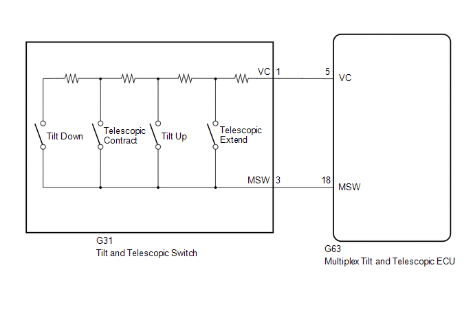
Different voltage values are sent to the multiplex tilt and telescopic ECU by operating the tilt and telescopic switch. The multiplex tilt and telescopic ECU then judges which motor and in which direction that motor should operate based on the voltage value.
WIRING DIAGRAM
PROCEDURE
| 1. | READ VALUE USING TECHSTREAM (TILT MANUAL SWITCH UP/DOWN, TELESCOPIC MANUAL SWITCH SHORT/LONG) |
(a) Turn the engine switch off.
(b) Connect the Techstream to the DLC3.
(c) Turn the engine switch on (IG).
(d) Turn the Techstream on.
(e) Read the Data List according to the display on the Techstream.
Body Electrical > Tilt&Telescopic > Data List| Tester Display |
|---|
| Tilt Manual Switch Up |
| Tilt Manual Switch Down |
| Telescopic Manual Switch Short |
| Telescopic Manual Switch Long |
| Tester Display | Measurement Item | Range | Normal Condition | Diagnostic Note |
|---|---|---|---|---|
| Tilt Manual Switch Up | Input state of tilt up switch | OFF or ON | - | - |
| Tilt Manual Switch Down | Input state of tilt down switch | OFF or ON | - | - |
| Telescopic Manual Switch Short | Input state of telescopic contract switch | OFF or ON | - | - |
| Telescopic Manual Switch Long | Input state of telescopic extend switch | OFF or ON | - | - |
OK:
The value of each Data List item changes in accordance with the operation of the switch.
| OK | .gif) | REPLACE MULTIPLEX TILT AND TELESCOPIC ECU |
|
.gif)
| 2. | CHECK HARNESS AND CONNECTOR (MULTIPLEX TILT AND TELESCOPIC ECU - TILT AND TELESCOPIC SWITCH) |
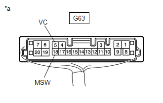
(a) Disconnect the G63 multiplex tilt and telescopic ECU connector.
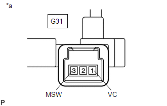
(b) Disconnect the G31 tilt and telescopic switch connector.
(c) Measure the resistance according to the value(s) in the table below.
Standard Resistance:
| Tester Connection | Condition | Specified Condition |
|---|---|---|
| G63-5 (VC) - G31-1 (VC) | Always | Below 1 Ω |
| G63-18 (MSW) - G31-3 (MSW) | Always | Below 1 Ω |
| G63-5 (VC) or G31-1 (VC) - Body ground | Always | 10 kΩ or higher |
| G63-18 (MSW) or G31-3 (MSW) - Body ground | Always | 10 kΩ or higher |
| NG | | REPAIR OR REPLACE HARNESS OR CONNECTOR |
|
| 3. | CHECK MULTIPLEX TILT AND TELESCOPIC ECU (VC TERMINAL VOLTAGE) |
| (a) Reconnect the G63 multiplex tilt and telescopic ECU connector. |
|
(b) Measure the voltage according to the value(s) in the table below.
Standard Voltage:
| Tester Connection | Condition | Specified Condition |
|---|---|---|
| G63-5 (VC) - G63-18 (MSW) | Engine switch on (IG) | 4.9 to 5.1 V |
| NG | | REPLACE MULTIPLEX TILT AND TELESCOPIC ECU |
|
| 4. | CHECK TILT AND TELESCOPIC SWITCH |
| (a) Remove the tilt and telescopic switch. Click here |
|
.gif)
(b) Measure the resistance according to the value(s) in the table below.
Standard Resistance:
| Tester Connection | Condition | Specified Condition |
|---|---|---|
| G31-1 (VC) - G31-3 (MSW) | Tilt up | 342 to 378 Ω |
| Tilt down | 1890.5 to 2089.5 Ω | |
| Telescopic contract | 750.5 to 829.5 Ω | |
| Telescopic extend | 152 to 168 Ω |
| OK | | REPLACE MULTIPLEX TILT AND TELESCOPIC ECU |
| NG | | REPLACE TILT AND TELESCOPIC SWITCH |
READ NEXT:
 IG Power Source Circuit
DESCRIPTION When the engine switch is turned on (IG), the IG power source circuit supplies positive (+) voltage to the multiplex tilt and telescopic ECU. WIRING DIAGRAM CAUTION / NOTICE / HINT NOTICE
Removal
REMOVAL CAUTION / NOTICE / HINT The necessary procedures (adjustment, calibration, initialization or registration) that must be performed after parts are removed and installed, or replaced during stee
SEE MORE:
Problem Symptoms Table
PROBLEM SYMPTOMS TABLE HINT:
Use the table below to help determine the cause of problem symptoms. If multiple suspected areas are listed, the potential causes of the symptoms are listed in order of probability in the "Suspected Area" column of the table.
Check each system by checking the suspec
Installation
INSTALLATION PROCEDURE 1. INSTALL NO. 1 FUEL TANK CUSHION (for TMMK Made) (a) Install 2 new No. 1 fuel tank cushions to the fuel tank assembly. 2. INSTALL NO. 2 FUEL TANK CUSHION (for TMMK Made) (a) Install a new No. 2 fuel tank cushion to the fuel tank assembly. 3. INSTALL FUEL TANK MAIN TUBE SUB-A
