Lexus ES: Thermostat
Components
COMPONENTS
ILLUSTRATION
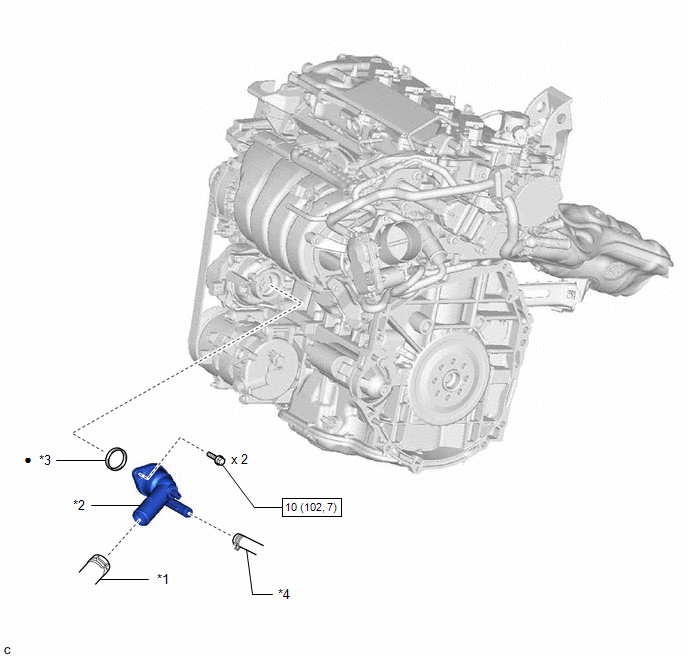
| *1 | NO. 2 RADIATOR HOSE | *2 | WATER INLET WITH THERMOSTAT SUB-ASSEMBLY |
| *3 | GASKET | *4 | NO. 7 WATER BY-PASS HOSE |
.png) | N*m (kgf*cm, ft.*lbf): Specified torque | ● | Non-reusable part |
Inspection
INSPECTION
PROCEDURE
1. INSPECT WATER INLET WITH THERMOSTAT SUB-ASSEMBLY
CAUTION:
- Do not put your hands into the water that has been heated for the inspection.
- Touching the heated water could result in burns.
.png)
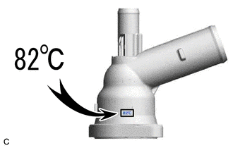
HINT:
The valve opening temperature is inscribed on the water inlet with thermostat sub-assembly.
(a) Immerse the water inlet with thermostat sub-assembly in water and then gradually heat the water.
NOTICE:
Do not allow any water to come into contact with the connector of the water inlet with thermostat sub-assembly.
(b) Check that the valve of the water inlet with thermostat sub-assembly opens at the specified temperature.
Standard Valve Opening Temperature:
80 to 84°C (176 to 183°F)
If the result is not as specified, replace the water inlet with thermostat sub-assembly.
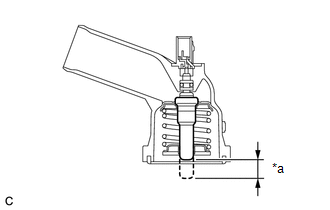
| (c) Check the valve lift. Standard Valve Lift: 8.0 mm (0.315 in.) or more at 95°C (203°F) If the result is not as specified, replace the water inlet with thermostat sub-assembly. |
|
(d) Check that the valve is fully closed when the water inlet with thermostat sub-assembly is at low temperatures (below 72°C (162°F)).
If it is not fully closed, replace the water inlet with thermostat sub-assembly.
(e) Measure the resistance according to the value(s) in the table below.
Standard Resistance:
| Tester Connection | Condition | Specified Condition |
|---|---|---|
| 1 - 2 | Always | 10.6 to 14.2 Ω |
If the result is not as specified, replace the water inlet with thermostat sub-assembly.
Installation
INSTALLATION
CAUTION / NOTICE / HINT
NOTICE:
This procedure includes the installation of small-head bolts. Refer to Small-Head Bolts of Basic Repair Hint to identify the small-head bolts.
Click here .gif)
PROCEDURE
1. INSTALL WATER INLET WITH THERMOSTAT SUB-ASSEMBLY
(a) Install a new gasket to the water inlet with thermostat sub-assembly.
HINT:
Be sure to clean the contact surfaces.
(b) Using an 8 mm socket wrench, install the water inlet with thermostat sub-assembly with the 2 bolts.
Torque:
10 N·m {102 kgf·cm, 7 ft·lbf}
(c) Connect the No. 7 water by-pass hose to the water inlet with thermostat sub-assembly and slide the clip to secure it.
(d) Connect the water inlet with thermostat sub-assembly connector.
2. CONNECT NO. 2 RADIATOR HOSE
Click here
3. INSTALL GENERATOR ASSEMBLY
Click here
4. ADD ENGINE COOLANT
Click here
5. INSPECT FOR COOLANT LEAK
Click here
READ NEXT:
 Water Pump
ComponentsCOMPONENTS ILLUSTRATION *1 ENGINE WATER PUMP ASSEMBLY (WATER INLET HOUSING) *2 GASKET *3 STUD BOLT - - N*m (kgf*cm, ft.*lbf): Specified torque ● Non-reusabl
SEE MORE:
Removal
REMOVAL CAUTION / NOTICE / HINT HINT:
Use the same procedure for the RH side and LH side.
The following procedure is for the LH side.
PROCEDURE 1. REMOVE HOOD SUPPORT ASSEMBLY NOTICE:
Avoid touching the piston rod as much as possible to prevent foreign matter from attaching to it. Be sure
PIG Power Supply Voltage (C1552,C1554)
DESCRIPTION When a malfunction is detected in the PIG power source and power supply relay system, the fail-safe function suspends power assist. DTC No. Detection Item DTC Detection Condition Trouble Area Warning Indicate Return-to-normal Condition Note C1552 PIG Power Supply Vol
