Lexus ES: Water Pump
Components
COMPONENTS
ILLUSTRATION
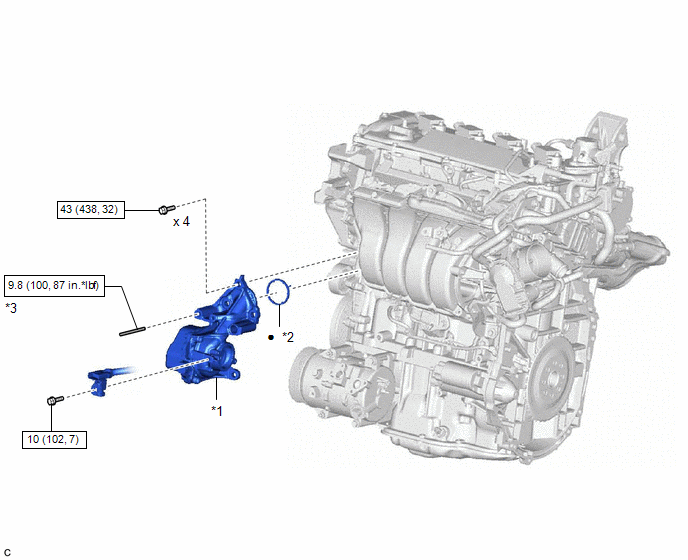
| *1 | ENGINE WATER PUMP ASSEMBLY (WATER INLET HOUSING) | *2 | GASKET |
| *3 | STUD BOLT | - | - |
.png) | N*m (kgf*cm, ft.*lbf): Specified torque | ● | Non-reusable part |
Installation
INSTALLATION
CAUTION / NOTICE / HINT
NOTICE:
This procedure includes the installation of small-head bolts. Refer to Small-Head Bolts of Basic Repair Hint to identify the small-head bolts.
Click here .gif)
PROCEDURE
1. INSTALL ENGINE WATER PUMP ASSEMBLY (WATER INLET HOUSING)
(a) Using an E8 "TORX" socket wrench, install the stud bolt.
Torque:
9.8 N·m {100 kgf·cm, 87 in·lbf}
(b) Install a new gasket to the engine water pump assembly (water inlet housing).
HINT:
Be sure to clean the contact surfaces.
(c) Install the engine water pump assembly (water inlet housing) to the cylinder block assembly with the 4 bolts.
Torque:
43 N·m {438 kgf·cm, 32 ft·lbf}
(d) Connect the engine water pump assembly (water inlet housing) connector.
| (e) Align the protrusion of the engine water pump assembly (water inlet housing) with the cutout in the sensor wire clamp. |
|
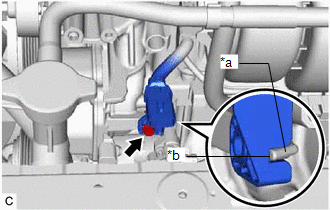
(f) Using an 8 mm socket wrench, connect the sensor wire to the engine water pump assembly (water inlet housing) with the bolt.
Torque:
10 N·m {102 kgf·cm, 7 ft·lbf}
(g) Connect the sensor wire connector.
2. INSTALL WATER INLET WITH THERMOSTAT SUB-ASSEMBLY
Click here
READ NEXT:
 Components
COMPONENTS ILLUSTRATION *1 REAR FLOOR SIDE MEMBER COVER - - N*m (kgf*cm, ft.*lbf): Specified torque - - ILLUSTRATION *1 CANISTER (CHARCOAL CANISTER ASSEMBLY) *2 LEAK
SEE MORE:
Drive Motor "A" Control Module Unexpected Operation (P0A1B94)
DTC SUMMARY MALFUNCTION DESCRIPTION The hybrid vehicle control ECU monitors the motor generator control ECU (MG ECU). The cause of this malfunction may be the following: Motor generator control ECU internal malfunction
Motor generator control ECU (MG ECU) malfunction
DESCRIPTION The hybrid veh
Camshaft Position "B" - Actuator Bank 1 Circuit Open (P001313,P002313)
DESCRIPTION The Variable Valve Timing (VVT) system adjusts the exhaust valve timing to improve driveability. The engine oil pressure turns the VVT controller to adjust the valve timing. The cam timing oil control solenoid assembly operates according to signals received from the ECM to control the po
