Lexus ES: PIG Power Supply Voltage (C1552,C1554)
DESCRIPTION
When a malfunction is detected in the PIG power source and power supply relay system, the fail-safe function suspends power assist.
| DTC No. | Detection Item | DTC Detection Condition | Trouble Area | Warning Indicate | Return-to-normal Condition | Note |
|---|---|---|---|---|---|---|
| C1552 | PIG Power Supply Voltage | PIG power source circuit malfunction |
| EPS warning light: Comes on | Engine switch on (IG) again | - |
| C1554 | Power Supply Relay Failure | Power source relay circuit malfunction |
| EPS warning light: Comes on | Engine switch on (IG) again | - |
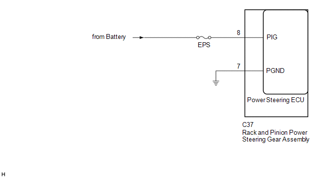
WIRING DIAGRAM
CAUTION / NOTICE / HINT
NOTICE:
-
If the rack and pinion power steering gear assembly has been replaced, perform assist map writing and torque sensor zero point calibration.
Click here
.gif)
- Inspect the fuses for circuits related to this system before performing the following procedure.
PROCEDURE
| 1. | CHECK HARNESS AND CONNECTOR (RACK AND PINION POWER STEERING GEAR ASSEMBLY - BODY GROUND) |
(a) Disconnect the C37 rack and pinion power steering gear assembly connector.
.png)
| *a | Front view of wire harness connector (to Rack and Pinion Power Steering Gear Assembly) | - | - |
(b) Measure the voltage according to the value(s) in the table below.
Standard Voltage:
| Tester Connection | Condition | Specified Condition |
|---|---|---|
| C37-8 (PIG) - Body ground | Always | 9 to 16 V |
(c) Measure the resistance according to the value(s) in the table below.
Standard Resistance:
| Tester Connection | Condition | Specified Condition |
|---|---|---|
| C37-7 (PGND) - Body ground | Always | Below 1 Ω |
| OK | .gif) | REPLACE RACK AND PINION POWER STEERING GEAR ASSEMBLY |
| NG | | REPAIR OR REPLACE HARNESS OR CONNECTOR |
READ NEXT:
 Error in Matching of ECUs (C1567)
DESCRIPTION The power steering ECU (rack and pinion power steering gear assembly) determines whether an incompatible ECM or skid control ECU (brake actuator assembly) is installed based on the identif
Error in Matching of ECUs (C1567)
DESCRIPTION The power steering ECU (rack and pinion power steering gear assembly) determines whether an incompatible ECM or skid control ECU (brake actuator assembly) is installed based on the identif
Assist Map Number Un-Writing (C1581)
DESCRIPTION This DTC will be stored if the power steering ECU (rack and pinion power steering gear assembly) determines that the assist map is not written in the ECU. DTC No. Detection Item DTC
SEE MORE:
Front Wiper Rubber
Components
COMPONENTS
ILLUSTRATION
*1
FRONT WIPER BLADE
*2
WIPER RUBBER
*3
FRONT WIPER RUBBER BACKING PLATE
-
-
Removal
REMOVAL
CAUTION / NOTICE / HINT
NOTICE:
Make sure to hold the f
Precaution
PRECAUTION PRECAUTION FOR DISCONNECTING CABLE FROM NEGATIVE AUXILIARY BATTERY TERMINAL NOTICE: When disconnecting the cable from the negative (-) auxiliary battery terminal, initialize the following system(s) after the cable is reconnected: System See Procedure Lane Control System (for HV M
