Lexus ES: Removal
REMOVAL
CAUTION / NOTICE / HINT
HINT:
- Use the same procedure for the RH side and LH side.
- The following procedure is for the LH side.
PROCEDURE
1. REMOVE HOOD SUPPORT ASSEMBLY
NOTICE:
- Avoid touching the piston rod as much as possible to prevent foreign matter from attaching to it. Be sure to hold the cylinder while servicing.
- Do not wear cotton gloves or other similar materials when handling the piston rod. Fibers may attach to the rod and result in gas leaks.
- Do not apply any horizontal load to the hood support assembly in order to prevent the piston rod from deforming.
| (a) Using a screwdriver with its tip wrapped with protective tape, slightly raise the 2 stop rings as shown in the illustration. NOTICE:
|
|
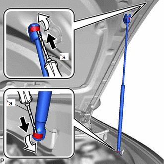
(b) Disengage the 2 ball joints to remove the hood support assembly.
NOTICE:
Remove the hood support assembly while supporting the hood sub-assembly by hand.
2. REMOVE HOOD STAY BRACKET
| (a) Remove the bolt. |
|
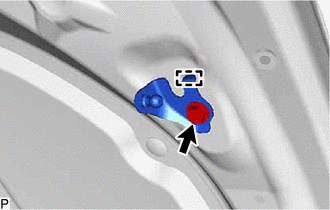
(b) Disengage the guide to remove the hood stay bracket.
3. REMOVE COOL AIR INTAKE DUCT SEAL
Click here .gif)
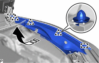
4. REMOVE NO. 3 COWL TOP PANEL INSULATOR
Click here
5. REMOVE FRONT FENDER SPLASH SHIELD SUB-ASSEMBLY
(a) Disengage the 3 clips.
.png) | Remove in this Direction |
(b) Disengage the 2 guides and remove the front fender splash shield sub-assembly as shown in the illustration.
6. REMOVE HOOD SUPPORT BRACKET
| (a) Remove the bolt. |
|
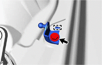
(b) Disengage the guide to remove the hood support bracket.
READ NEXT:
 Installation
INSTALLATION CAUTION / NOTICE / HINT HINT:
Use the same procedure for the RH side and LH side.
The following procedure is for the LH side.
PROCEDURE 1. INSTALL HOOD SUPPORT BRACKET (a) Engage
Disposal
DISPOSAL PROCEDURE 1. DISPOSE OF HOOD SUPPORT ASSEMBLY (a) Secure the hood support assembly horizontally in a vise with the piston rod pulled out. (b) Wearing safety glasses, gradually cut a part w
SEE MORE:
Control Module Communication Bus Off (U0073,U0100,U0101,U0126,U0129,U0142,U0155,U0242)
DESCRIPTION These DTCs are stored if a CAN communication malfunction occurs between the headlight ECU sub-assembly LH and other ECUs. for LED Type Turn Signal Light DTC No. Detection Item DTC Detection Condition Trouble Area DTC Output from U0073 Control Module Communication Bus Off
Power Window Motor Malfunction (B2311)
DESCRIPTION The power window regulator motor assemblies are operated by the multiplex network master switch assembly, power window regulator switch assembly or rear power window regulator switch assemblies. The power window regulator motor assemblies have motor, regulator and ECU functions. This DTC
