Lexus ES: Terminals Of Ecu
TERMINALS OF ECU
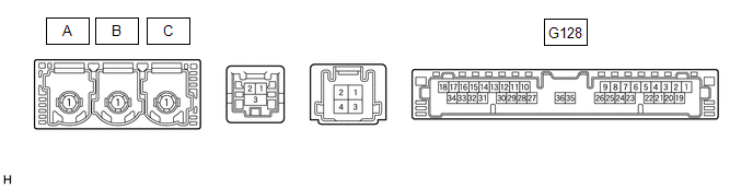
| Terminal No. (Symbol) | Wiring Color | Terminal Description | Condition | Specified Condition |
|---|---|---|---|---|
| G128-1 (+B) - G128-20 (E) | BR - W-B | Power source (+B) | Always | 11 to 14 V |
| G128-3 (SIG-) - G128-20 (E) | B - W-B | Ground | Always | Below 1 V |
| G128-4 (IND1) - G128-20 (E) | LG - W-B | Manual (SOS) switch red indicator illumination signal | For 2 seconds after turning the engine switch on (IG) | 1 to 8.5 V |
| Engine switch off | Below 1 V | |||
| G128-5 (MCVD) - G128-20 (E) | B - W-B | Telephone microphone assembly power supply | Engine switch on (ACC) | 4 to 6 V |
| Engine switch off | Below 1 V | |||
| G128-6 (MCI+) - G128-20 (E) | W - W-B | Receive microphone voice signal | Voice being input to telephone microphone assembly | A waveform synchronized with microphone voice signal is input |
| G128-7 (MCI-) - G128-20 (E) | R - W-B | Receive microphone voice signal | Always | Below 1 V |
| G128-13 (GSW) - G128-20 (E) | Y - W-B | Collision detection signal | Engine switch on (IG) | Pulse generation (Refer to waveform1) |
| G128-19 (IG2) - G128-20 (E) | P - W-B | Power source (IG) | Engine switch on (IG) | 11 to 14 V |
| Engine switch off | Below 1 V | |||
| G128-20 (E) - Body ground | W-B - Body ground | Ground | Always | Below 1 Ω |
| G128-21 (SIG1) - G128-3 (SIG-) | R - G | Manual (SOS) switch button condition signal | Manual (SOS) switch not pressed | 1.3 to 1.9 V |
| Manual (SOS) switch pressed | 0.5 to 0.8 V | |||
| G128-22 (IND2) - G128-20 (E) | G - W-B | Manual (SOS) switch green indicator illumination signal | For 2 seconds after turning the engine switch on (IG) | 1 to 8.5 V |
| Engine switch off | Below 1 V | |||
| G128-23 (SGND) - G128-20 (E) | Shielded - W-B | Shield ground | Always | Below 1 Ω |
| G128-25 (CANP) | R | CAN communication signal | - | - |
| G128-26 (CANN) | W | CAN communication signal | - | - |
CHECK DCM (TELEMATICS TRANSCEIVER)
(a) Oscilloscope waveform:
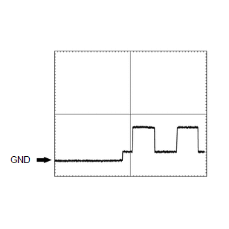
(1) Waveform 1
| Item | Condition |
|---|---|
| Tester connection | G128-13 (GSW) - G128-20 (E) |
| Tool setting | 5.0 V/DIV., 20 ms/DIV. |
| Vehicle condition | Engine switch on (IG) |
CHECK RADIO RECEIVER ASSEMBLY
w/o Navigation System: Click here .gif)
w/ Navigation System: Click here
READ NEXT:
 Unable To Connect To Call Center
DESCRIPTION This may occur when the intensity of telephone radio frequency was very weak, or the safety connect system has a malfunction and a DTC is set. PROCEDURE 1. CHECK COMMUNICATION SERVIC
Vehicle Control History
VEHICLE CONTROL HISTORY NOTICE: Make sure to record any output Vehicle Control History codes before clearing them and checking the Vehicle Control History again. CHECK VEHICLE CONTROL HISTORY NOTICE:
SEE MORE:
Remote Touch Screen Does not Generate Vibration Feedback
DESCRIPTION When each button displayed on the multi-display assembly is selected via remote touch screen operation, the remote touch screen generates vibration feedback according to communication between the remote touch and radio receiver assembly. CAUTION / NOTICE / HINT NOTICE:
Depending on th
Replacement
REPLACEMENT
PROCEDURE
1. REMOVE FRONT WHEEL OPENING EXTENSION PAD RH
Click here
2. REMOVE FRONT WHEEL OPENING EXTENSION PAD LH
Click here
3. REMOVE NO. 1 ENGINE UNDER COVER
Click here
4. REMOVE NO. 2 ENGINE UNDER COVER ASSEMBLY
Click here
5. REPLACE HYBRID TRANSAXLE FLU
