Lexus ES: Terminals Of Ecu
TERMINALS OF ECU
CHECK OUTER MIRROR CONTROL ECU ASSEMBLY (DRIVER DOOR)

(a) Disconnect the J28 outer mirror control ECU assembly (driver door) connector.
(b) Measure the voltage and resistance according to the value(s) in the table below.
HINT:
Measure the values on the wire harness side with the connector disconnected.
| Terminal No. (Symbol) | Wiring Color | Terminal Description | Condition | Specified Condition |
|---|---|---|---|---|
| J28-14 (BDR) - Body ground | GR - Body ground | +B power supply | Always | 11 to 14 V |
| J28-6 (CPUB) - Body ground | LA-L - Body ground | +B power supply | Always | 11 to 14 V |
| J28-5 (SIG) - Body ground | LA-B - Body ground | Ignition power supply | Engine switch off → on (IG) | Below 1 V → 11 to 14 V |
| J28-7 (GND) - Body ground | W-B - Body ground | Ground | Always | Below 1 Ω |
(c) Reconnect the J28 outer mirror control ECU assembly (driver door) connector.
(d) Measure the voltage according to the value(s) in the table below.
| Terminal No. (Symbol) | Wiring Color | Terminal Description | Condition | Specified Condition |
|---|---|---|---|---|
| z20-3 (MR) - Body ground | G - Body ground | Power retract mirror motor drive voltage | Outer rear view mirror assembly (driver door) being retracted | 11 to 14 V |
| Outer rear view mirror assembly (driver door) stopped | Below 1 V | |||
| z20-11 (MF) - Body ground | L - Body ground | Power retract mirror motor drive voltage | Outer rear view mirror assembly (driver door) returning | 11 to 14 V |
| Outer rear view mirror assembly (driver door) stopped | Below 1 V | |||
| z20-1 (MV) - z20-10 (M+) | W - B | Vertical mirror motor drive voltage | Driver door mirror surface moving upward → stopped | 11 to 14 V → Below 1 V |
| z20-10 (M+) - z20-1 (MV) | B - W | Vertical mirror motor drive voltage | Driver door mirror surface moving downward → stopped | 11 to 14 V → Below 1 V |
| z20-10 (M+) - z20-9 (MH) | B - R | Horizontal mirror motor drive voltage | Driver door mirror surface moving right → stopped | 11 to 14 V → Below 1 V |
| z20-9 (MH) - z20-10 (M+) | R - B | Horizontal mirror motor drive voltage | Driver door mirror surface moving left → stopped | 11 to 14 V → Below 1 V |
| z20-5 (VC) - z20-14 (E1) | SB - GR | Mirror position sensor power supply | Engine switch on (IG) | 4.55 to 5.45 V |
| Engine switch off | Below 1 V | |||
| z20-6 (VSRL) - J28-7 (GND) | V - W-B | Mirror position sensor signal | Engine switch on (IG) | 0 to 5 V |
| z20-13 (HSRL) - J28-7 (GND) | LG - W-B | Mirror position sensor signal | Engine switch on (IG) | 0 to 5 V |
| z20-4 (H+) - z20-12 (GND) | BR-W - BR | Mirror heater relay drive voltage | Mirror heater switch (rear window defogger switch) on | 11 to 14 V |
| J28-4 (M3) - J28-7 (GND) | G - W-B | M3 switch signal for seat memory switch | M3 switch on | Below 1 V |
| M3 switch off | 11 to 14 V | |||
| J28-3 (M2) - J28-7 (GND) | R - W-B | M2 switch signal for seat memory switch | M2 switch on | Below 1 V |
| M2 switch off | 11 to 14 V | |||
| J28-2 (M1) - J28-7 (GND) | BR - W-B | M1 switch signal for seat memory switch | M1 switch on | Below 1 V |
| M1 switch off | 11 to 14 V | |||
| J28-1 (MM) - J28-7 (GND) | GR - W-B | SET switch signal for seat memory switch | SET switch on | Below 1 V |
| SET switch off | 11 to 14 V | |||
| Z20-4 (H+) - Z20-12 (GND) | BR-W - BR | Mirror heater relay drive voltage | Mirror heater switch (rear window defogger switch) on | 11 to 14 V |
| z20-7 (EC+) - z20-15 (EC-) | BR - B-L | Automatic glare-resistant EC mirror drive signal | Automatic glare-resistant EC mirror off → on | Below 1 V → 1.05 to 1.35 V |

CHECK OUTER MIRROR CONTROL ECU ASSEMBLY (FRONT PASSENGER DOOR)
(a) Disconnect the J6 outer mirror control ECU assembly (front passenger door) connector.
(b) Measure the voltage and resistance according to the value(s) in the table below.
HINT:
Measure the values on the wire harness side with the connector disconnected.
| Terminal No. (Symbol) | Wiring Color | Terminal Description | Condition | Specified Condition |
|---|---|---|---|---|
| J6-14 (BDR) - Body ground | GR - Body ground | +B power supply | Always | 11 to 14 V |
| J6-6 (CPUB) - Body ground | LA-L - Body ground | +B power supply | Always | 11 to 14 V |
| J6-5 (SIG) - Body ground | LA-B - Body ground | Ignition power supply | Engine switch off → on (IG) | Below 1 V → 11 to 14 V |
| J6-7 (GND) - Body ground | W-B - Body ground | Ground | Always | Below 1 Ω |
(c) Reconnect the J6 outer mirror control ECU assembly (front passenger door) connector.
(d) Measure the voltage according to the value(s) in the table below.
| Terminal No. (Symbol) | Wiring Color | Terminal Description | Condition | Specified Condition |
|---|---|---|---|---|
| z19-3 (MR) - Body ground | G - Body ground | Power retract mirror motor drive voltage | Outer rear view mirror assembly (front passenger door) being retracted | 11 to 14 V |
| Outer rear view mirror assembly (front passenger door) stopped | Below 1 V | |||
| z19-11 (MF) - Body ground | L - Body ground | Power retract mirror motor drive voltage | Outer rear view mirror assembly (front passenger door) returning | 11 to 14 V |
| Outer rear view mirror assembly (front passenger door) stopped | Below 1 V | |||
| z19-1 (MV) - z19-10 (M+) | W - B | Vertical mirror motor drive voltage | Front passenger door mirror surface moving upward → stopped | 11 to 14 V → Below 1 V |
| z19-10 (M+) - z19-1 (MV) | B - W | Vertical mirror motor drive voltage | Front passenger door mirror surface moving downward → stopped | 11 to 14 V → Below 1 V |
| z19-10 (M+) - z19-9 (MH) | B - R | Horizontal mirror motor drive voltage | Front passenger door mirror surface moving right → stopped | 11 to 14 V → Below 1 V |
| z19-9 (MH) - z19-10 (M+) | R - B | Horizontal mirror motor drive voltage | Front passenger door mirror surface moving left → stopped | 11 to 14 V → Below 1 V |
| z19-5 (VC) - z19-14 (E1) | SB - GR | Mirror position sensor power supply | Engine switch on (IG) | 4.55 to 5.45 V |
| Engine switch off | Below 1 V | |||
| z19-6 (VSSR) - J6-7 (GND) | V - W-B | Mirror position sensor signal | Engine switch on (IG) | 0 to 5 V |
| z19-13 (HSSR) - J6-7 (GND) | LG - W-B | Mirror position sensor signal | Engine switch on (IG) | 0 to 5 V |
| z19-4 (H+) - z19-12 (GND) | BR-W - BR | Mirror heater relay drive voltage | Mirror heater switch (rear window defogger switch) on | 11 to 14 V |
| z19-7 (EC+) - z19-15 (EC-) | BR - B-L | Automatic glare-resistant EC mirror drive signal | Automatic glare-resistant EC mirror off → on | Below 1 V → 1.05 to 1.35 V |
CHECK MAIN BODY ECU (MULTIPLEX NETWORK BODY ECU) AND INSTRUMENT PANEL JUNCTION BLOCK ASSEMBLY
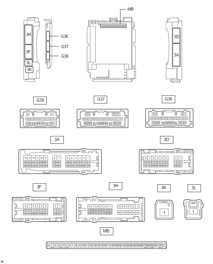
(a) Disconnect the instrument panel junction block assembly and main body ECU (multiplex network body ECU) connectors.
Click here .gif)
(b) Measure the resistance according to the value(s) in the table below.
HINT:
Measure the values on the wire harness side with the connectors connected.
| Terminal No. (Symbol) | Wiring Color | Terminal Description | Condition | Specified Condition |
|---|---|---|---|---|
| G36-19 (GND2) - Body ground | W-B - Body ground | Ground | Always | Below 1 Ω |
(c) Reconnect the instrument panel junction block assembly connectors.
(d) Measure the resistance and voltage according to the value(s) in the table below.
HINT:
Measure the values on the wire harness side with the connector disconnected.
| Terminal No. (Symbol) | Wiring Color | Terminal Description | Condition | Specified Condition |
|---|---|---|---|---|
| MB-31 (BECU) - Body ground | - | Battery power supply | Always | 11 to 14 V |
| MB-32 (IG) - Body ground | - | Ignition power supply (IG signal) | Engine switch on (IG) | 11 to 14 V |
| Engine switch off | Below 1 V | |||
| MB-30 (ACC) - Body ground | - | Ignition power supply (ACC signal) | Engine switch on (ACC) | 11 to 14 V |
| Engine switch off | Below 1 V | |||
| MB-11 (GND1) - Body ground | - | Ground | Always | Below 1 Ω |
(e) Connect the main body ECU (multiplex network body ECU) connectors.
(f) Measure the voltage according to the value(s) in the table below.
| Tester Connection | Wiring Color | Terminal Description | Condition | Specified Condition |
|---|---|---|---|---|
| G38-7 (MIRB) - G38-9 (MIRE) | V - W | Mirror adjust switch signal |
| Below 1.7 V |
| Below 2.7 V | |||
| Below 3.5 V | |||
| Below 4 V | |||
| 3.8 to 5 V | |||
| G38-8 (MIRS) - G38-9 (MIRE) | GR - W | Mirror select switch signal |
| Below 2 V |
| Below 1 V | |||
| 3.8 to 5.0 V | |||
| G38-16 (RET) - G38-9 (MIRE) | B - W | Retractable outer mirror switch signal |
| Pulse generation (See waveform 1 or 2) |
| Below 1 V | |||
| G38-6 (AMR) - G38-9 (MIRE) | BE - W | Retractable outer mirror switch signal |
| Pulse generation (See waveform 1 or 2) |
| Below 1 V |
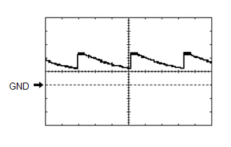
(g) Using an oscilloscope, check waveform 1.
Waveform 1 (Reference)| Item | Content |
|---|---|
| Tester Connection | G38-16 (RET) or G38-6 (AMR) - G38-9 (MIRE) |
| Tool Setting | 5 V/DIV., 20 ms/DIV. |
| Condition |
|
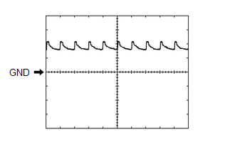
(h) Using an oscilloscope, check waveform 2.
Waveform 2 (Reference)| Item | Content |
|---|---|
| Tester Connection | G38-16 (RET) or G38-6 (AMR) - G38-9 (MIRE) |
| Tool Setting | 5 V/DIV., 20 ms/DIV. |
| Condition |
|
READ NEXT:
 Diagnosis System
DIAGNOSIS SYSTEM CHECK DLC3 (a) Check the DLC3. Click here INSPECT BATTERY VOLTAGE (a) Measure the battery voltage. Standard Voltage: 11 to 14 V If the voltage is below 11 V, recharge or replace th
Data List / Active Test
DATA LIST / ACTIVE TEST DATA LIST NOTICE: In the table below, the values listed under "Normal Condition" are reference values. Do not depend solely on these reference values when deciding whether a pa
Dtc Check / Clear
DTC CHECK / CLEAR CHECK DTC (a) Connect the Techstream to the DLC3. (b) Turn the engine switch on (IG). (c) Turn the Techstream on. (d) Enter the following menus: Body Electrical / Mirror L or Mirror
SEE MORE:
Components
COMPONENTS ILLUSTRATION *1 ENGINE BALANCER ASSEMBLY *2 ENGINE OIL LEVEL SENSOR *3 NO. 2 OIL PAN SUB-ASSEMBLY *4 OIL PUMP ASSEMBLY *5 OIL PUMP BRACKET *6 OIL STRAINER SUB-ASSEMBLY *7 STIFFENING CRANKCASE ASSEMBLY *8 OIL STRAINER GASKET Tightening torque
Brake Hydraulic Pressure Malfunction (C164F)
DESCRIPTION When a malfunction signal sent from the skid control ECU via CAN communication is detected by the clearance warning ECU assembly, DTC C164F is stored. DTC No. Detection Item DTC Detection Condition Trouble Area C164F Brake Hydraulic Pressure Malfunction Brake master cyli
