Lexus ES: Terminals Of Ecu
TERMINALS OF ECU
HEATED STEERING WHEEL CONTROLLER (STEERING VIBRATION ECU)
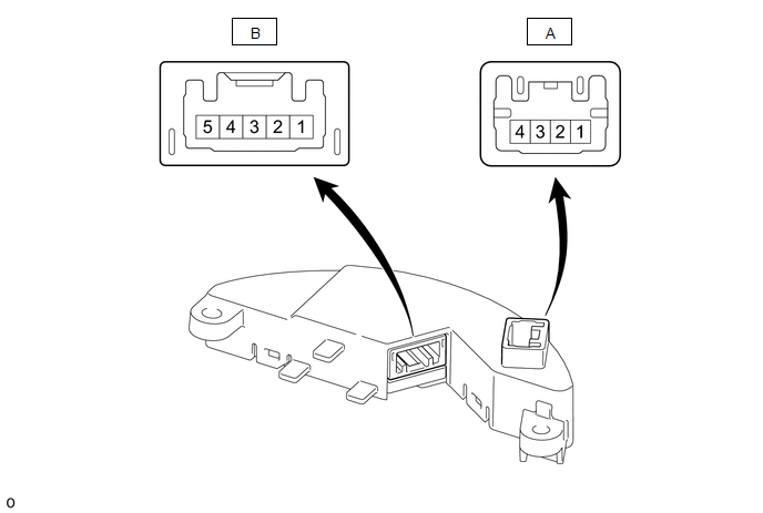
(a) Measure the voltage or resistance according to the value(s) in the table below.
HINT:
Perform the inspection from the harness side with the connectors connected.
| Terminal No. (Symbol) | Terminal Description | Condition | Specified Condition |
|---|---|---|---|
| A-1 (GND) - Body ground | Ground | Always | Below 1 Ω |
| A-3 (LIN2) - Body ground | LIN communication signal | Engine switch on (IG) | Pulse generation |
| A-4 (IG) - Body ground | IG power supply | Engine switch on (IG) | 11 to 14 V |
| B-1 (SH1) - Body ground | Heater output signal | Engine switch on (IG), Heated steering wheel system operating | Below 1 V |
| B-2 (TH1) - Body ground | Thermistor input signal | Engine switch on (IG), Heated steering wheel system operating | 11 to 14 V*1 |
| B-3 (TH2) - Body ground | Thermistor ground | Engine switch on (IG), Heated steering wheel system operating | 2.5 to 4.8 V*2 |
| B-4 (SH3) - Body ground | Heater ground | Engine switch on (IG), Heated steering wheel system operating | Below 1 V |
| B-5 (SH2) - Body ground | Heater ground | Engine switch on (IG), Heated steering wheel system operating | Below 1 V |
HINT:
- *1: The current to the heater turns ON/OFF depending on the temperature of the thermistor. As a result, it may take several minutes before a voltage value is output.
- *2: When ambient temperature is 0 to 40°C (32 to 104°F).
READ NEXT:
 Dtc Check / Clear
DTC CHECK / CLEAR CHECK DTC (a) Connect the Techstream to the DLC3. (b) Turn the engine switch on (IG). (c) Turn the Techstream on. (d) Enter the following menus: Body Electrical / Air Conditioner / T
Fail-safe Chart
FAIL-SAFE CHART DIAGNOSIS FUNCTION
Heated steering wheel controller (steering vibration ECU) has diagnosis function. Condition Detection Condition Response when malfunction detected Recove
Data List / Active Test
DATA LIST / ACTIVE TEST DATA LIST NOTICE: In the table below, the values listed under "Normal Condition" are reference values. Do not depend solely on these reference values when deciding whether a pa
SEE MORE:
Parts Location
PARTS LOCATION ILLUSTRATION *A for Manual Tilt and Manual Telescopic Steering Column *B for Power Tilt and Power Telescopic Steering Column *C w/ Power Trunk Lid System - - *1 MULTIPLEX NETWORK MASTER SWITCH ASSEMBLY *2 INSTRUMENT PANEL JUNCTION BLOCK ASSEMBLY - ECU-B N
Installation
INSTALLATION PROCEDURE 1. INSTALL LUGGAGE DOOR OPENING SWITCH (TRUNK AND FUEL SWITCH ASSEMBLY) (a) Engage the 2 claws to install the luggage door opening switch (trunk and fuel switch assembly) as shown in the illustration. Install in this Direction 2. INSTALL LOWER INSTRUMENT PANEL FINISH
