Lexus ES: Parts Location
PARTS LOCATION
ILLUSTRATION
.png)
| *A | for Manual Tilt and Manual Telescopic Steering Column | *B | for Power Tilt and Power Telescopic Steering Column |
| *C | w/ Power Trunk Lid System | - | - |
| *1 | MULTIPLEX NETWORK MASTER SWITCH ASSEMBLY | *2 | INSTRUMENT PANEL JUNCTION BLOCK ASSEMBLY - ECU-B NO. 2 FUSE - DOOR F/L FUSE - DOOR F/R FUSE - DOOR R/L FUSE - DOOR R/R FUSE - S/ROOF FUSE - STRG LOCK FUSE - ECU-B NO. 1 FUSE |
| *3 | STEERING LOCK ECU (STEERING LOCK ACTUATOR OR UPPER BRACKET ASSEMBLY) | *4 | ID CODE BOX (IMMOBILISER CODE ECU) |
| *5 | CERTIFICATION ECU (SMART KEY ECU ASSEMBLY) | *6 | MAIN BODY ECU (MULTIPLEX NETWORK BODY ECU) |
| *7 | ECU-DCC NO. 2 FUSE | *8 | DLC3 |
ILLUSTRATION
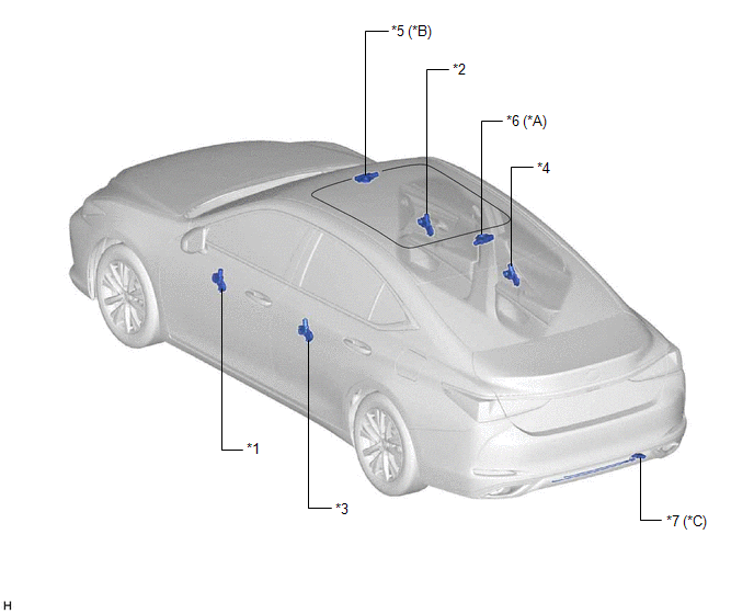
| *A | w/ Panoramic Moon Roof System | *B | w/ Sliding Roof System |
| *C | w/ Power Trunk Lid System | - | - |
| *1 | POWER WINDOW REGULATOR MOTOR ASSEMBLY (DRIVER DOOR) | *2 | POWER WINDOW REGULATOR MOTOR ASSEMBLY (FRONT PASSENGER DOOR) |
| *3 | POWER WINDOW REGULATOR MOTOR ASSEMBLY (REAR LH DOOR) | *4 | POWER WINDOW REGULATOR MOTOR ASSEMBLY (REAR RH DOOR) |
| *5 | SLIDING ROOF ECU (SLIDING ROOF DRIVE GEAR SUB-ASSEMBLY) | *6 | SLIDING ROOF ECU (SLIDING ROOF DRIVE GEAR ASSEMBLY) |
| *7 | KICK DOOR CONTROL SENSOR | - | - |
READ NEXT:
 Precaution
PRECAUTION PRECAUTION FOR DISCONNECTING CABLE FROM NEGATIVE BATTERY TERMINAL NOTICE: When disconnecting the cable from the negative (-) battery terminal, initialize the following systems after the cab
Tire Pressure Monitor ECU Communication Stop Mode
DESCRIPTION Detection Item Symptom Trouble Area Tire Pressure Monitor ECU Communication Stop Mode Any of the following conditions are met:
Communication stop for "Tire Pressure" is ind
SEE MORE:
Right Front Wheel Speed Sensor Circuit Short to Ground or Open (C050614)
DESCRIPTION Refer to DTC C050612 Click here DTC No. Detection Item DTC Detection Condition Trouble Area C050614 Right Front Wheel Speed Sensor Circuit Short to Ground or Open A short or open circuit is detected in the speed sensor signal circuit for 0.12 seconds or more.
Fron
Lost Communication with Body Control Module "B" Missing Message (U014287,U015587,U020887)
DESCRIPTION The multiplex tilt and telescopic ECU receives signals from the main body ECU (multiplex network body ECU), combination meter assembly and position control ECU assembly (driver seat) via CAN communication. DTC No. Detection Item DTC Detection Condition Trouble Area U014287
